Do you have a question about the Toshiba RAS-M18YAV-E and is the answer not in the manual?
Details product capabilities, power, dimensions, and operating parameters.
Details performance metrics for combined indoor unit operations in cooling and heating.
Illustrates compressor speed vs. current and capacity variation vs. temperature.
Illustrates compressor speed vs. current and capacity variation vs. temperature.
Provides electrical specifications for cooling and heating modes, including component data.
Covers essential safety precautions for R410A installation and servicing.
Details installation requirements for refrigerant piping systems.
Describes materials and types of joints for refrigerant piping.
Explains how to process piping materials, including cutting and burr removal.
Outlines procedures and precautions for flare connecting, including torque values.
Lists tools required for R410A installation and general tools.
Details the step-by-step process for recharging refrigerant.
Covers essential pipe joining techniques for refrigerant systems.
Lists various brazing filler materials.
Explains the purpose and types of flux used in brazing.
Describes techniques to prevent oxidation during brazing.
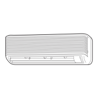
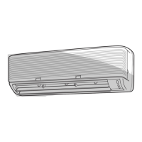
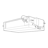
Provides detailed diagrams and dimensions for the indoor unit.
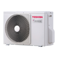
Provides detailed diagrams and dimensions for the outdoor unit.
Shows the electrical wiring schematic for the indoor unit.
Shows the electrical wiring schematic for the outdoor unit.
Lists electrical parts and specifications for indoor units.
Lists electrical parts and specifications for outdoor units.
Illustrates the refrigerant flow paths for cooling and heating.
Details performance metrics under various operating conditions.
Diagrams control functions and signal flow for the indoor unit.
Diagrams control functions and signal flow for the outdoor unit.
Explains the overall control logic and roles of controllers.
Details how cooling capacity is controlled via compressor speed.
Explains how current is managed to prevent overloads.
Describes power factor improvement techniques.
Explains how to prevent indoor heat exchanger freezing.
Details the function of the Pulse Modulating Valve.
Explains the control of air flow louvers.
Details control of the indoor fan motor speed.
Explains control of the outdoor fan motor speed.
Provides a general description of the operation circuit.
Explains how to operate the unit in fan-only mode.
Explains cooling operation, including capacity control and prevent-freezing.
Limits compressor speed based on indoor fan speed.
Explains how louvers are controlled.
Explains control based on discharge temperature.
Details control logic for Economy mode.
Explains the DRY operation mode.
Details heating operation, including cold draft prevention.
Explains how automatic operation selects modes.
Overviews temporary operation modes.
Details how temporary auto operation works.
Details how temporary cooling operation works.
Explains the auto-restart feature for power interruptions.
Provides steps to enable the auto-restart feature.
Provides steps to disable the auto-restart feature.
Explains how power failures affect timer operations.
Explains the remote control functions and indicators.
Identifies components of the remote control.
Explains the display indicators on the remote.
Crucial safety guidelines and precautions for installation.
General installation steps for the indoor unit.
Criteria for selecting the indoor unit installation location.
Procedures for preparing the wall for installation.
Details how to connect the inter-unit wiring.
Details steps for connecting pipes and drain hoses.
Instructions for proper drainage installation.
How to securely mount the indoor unit.
How to set the selector switch on the remote control.
How to set the selector switch on the remote control.
Steps for checking and testing the installed unit.
General installation steps for the outdoor unit.
Lists parts required for outdoor unit installation.
Specifies requirements for refrigerant piping.
Lists optional parts for local supply.
Lists optional parts sold separately.
Procedures for connecting refrigerant piping.
Proper torque for flare nut connections.
Details the steps for evacuating the system.
Covers electrical work procedures, wiring, and power supply.
Final checks and testing after installation.
How to check for wiring or piping errors.
Lists specialized tools for R410A systems.
Initial troubleshooting steps to verify basic conditions.
Verifying the power supply status.
Verifying the input voltage levels.
Identifying normal operating behaviors that may seem like faults.
Methods for initial fault diagnosis.
Interpreting LED codes for self-diagnosis of indoor unit faults.
Overview of troubleshooting using remote control diagnostic codes.
How to perform self-diagnosis via the remote control.
Important safety and procedural cautions for performing service.
Diagnosing issues based on observed symptoms.
Diagnosing indoor unit issues based on symptoms.
Diagnosing problems related to inter-unit wiring and communication.
Detailed troubleshooting for specific error codes.
Interpreting outdoor unit LED codes for fault diagnosis.
Comprehensive troubleshooting guide for the outdoor unit.
A diagnostic flowchart for the inverter assembly in the outdoor unit.
General methods for checking main system components.
Procedures for inspecting the indoor unit's P.C. board.
Layout diagrams of P.C. boards with component locations.
Checking procedures for various indoor unit parts.
Checking procedures for various outdoor unit parts.
Detailed checks for electrolytic capacitors and converter modules.
Method to determine the condition of the outdoor fan motor.
Step-by-step guide for replacing main parts of the indoor unit.
Steps for detaching and attaching the outdoor unit's outer parts.
Exploded view and parts list for the indoor unit.
Exploded view and parts list for the outdoor unit.
Layout diagrams of P.C. boards in the outdoor unit.
| Cooling Capacity | 5.0 kW |
|---|---|
| Power Supply | 220-240V, 50Hz |
| Refrigerant | R410A |
| Energy Efficiency Ratio (EER) | 3.21 |
| Coefficient of Performance (COP) | 3.61 |
| Outdoor Unit Dimensions (W x H x D) | 780 x 550 x 290 mm |
| Noise Level (Indoor) | 42 dB(A) |
| Noise Level (Outdoor) | 52 dB(A) |
| Type | Split System Air Conditioner |