Do you have a question about the Toshiba RAS-M18YACV-E and is the answer not in the manual?
Detailed technical specifications for indoor and outdoor units, including capacities, power, noise, and dimensions.
Performance data for cooling and heating when indoor units are combined with others.
Graphs illustrating cooling and heating operation characteristics and capacity variation ratios.
Detailed electrical specifications, including voltages, currents, and power supply data for cooling.
Safety precautions for handling R410A refrigerant during installation and servicing.
Details on copper pipes and joints suitable for R410A refrigerant installation.
Lists tools required for R410A refrigerant handling and installation, including specialized tools.
Step-by-step guide for recharging refrigerant, including vacuum pump usage and charging configuration.
Information on brazing filler materials and the necessity and types of flux for pipe joining.
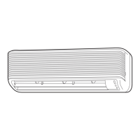
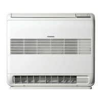
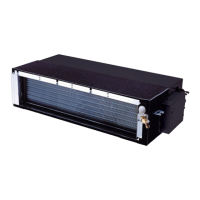
Diagrams and dimensions for the indoor unit, including mounting details.
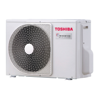
Diagrams showing dimensions and mounting arrangements for the outdoor unit.
Schematic diagram illustrating the electrical connections within the indoor unit.
Electrical schematic for the outdoor unit, showing connections for various components.
List and specifications of electrical parts used in the indoor unit.
List and specifications of electrical parts used in the outdoor unit.
Diagram illustrating the flow of refrigerant through the indoor and outdoor units.
Data on operating conditions for cooling and heating modes, including pressures and temperatures.
Block diagram showing the control functions and signal flow within the indoor unit.
Block diagram illustrating the control logic and components of the outdoor unit.
Overview of how the indoor and outdoor units control the air conditioner's operation.
Details on automatic, temporary auto, and temporary cooling operation modes.
Explanation of how to set up and use the automatic restart function after a power outage.
Explanation of the remote control's buttons, display indications, and functions.
Essential safety precautions and warnings for installing the air conditioner.
Steps and guidelines for installing the indoor unit, including placement and hole cutting.
Guidelines for installing the outdoor unit, including placement, piping, and wiring.
Initial steps for confirming power supply and voltage before diagnosing issues.
Identifies specific operations that may appear as issues but are normal programmed functions.
Interpreting LED indicators on the indoor unit for self-diagnosis of faults.
Using the remote control to perform self-diagnosis and interpret check codes.
Diagnosing issues based on symptoms, starting with the indoor unit and power.
Diagnosing problems related to wiring, interconnecting cables, and serial signal communication.
Troubleshooting steps for specific error codes (1C, 1E) related to wiring, sensors, and leakage.
Understanding outdoor unit LEDs for diagnosing operational status and faults.
Summarized diagnosis process for the outdoor unit's inverter assembly, including checks for fuses and capacitors.
Procedures for checking key parts like the P.C. board, sensors, and motors for proper function.
Steps to determine if the outdoor fan motor is functional or faulty by checking its windings and resistance.
Step-by-step instructions for replacing major parts of the indoor unit, like the front panel and electrical assembly.
Procedures for detaching and attaching major parts of the outdoor unit, including cabinets and covers.
Exploded view diagram and parts list for the indoor unit.
Exploded view diagram and parts list for the outdoor unit.
Layout diagrams for the P.C. boards used in the outdoor unit, showing sensor connections.
| Brand | Toshiba |
|---|---|
| Model | RAS-M18YACV-E |
| Category | Air Conditioner |
| Language | English |