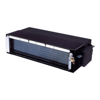
Do you have a question about the Toshiba RAS-M22SKV-E and is the answer not in the manual?
Safety precautions for R410A installation and servicing.
Guidelines for installing refrigerant piping with R410A.
Lists tools required for R410A installation and servicing.
Specific tools needed for R410A, including those for conventional refrigerant.
Step-by-step procedure for recharging R410A refrigerant.
Materials and methods for brazing refrigerant pipes.
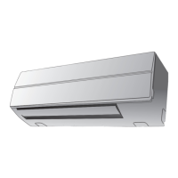
Exploded view and dimensions of the indoor unit.
Details electrical components and specifications for the indoor unit.
Schematic showing the refrigerant flow within the air conditioner.
Block diagram illustrating the control system of the indoor unit.
Overview of the air conditioner's control system and components.
Detailed explanation of basic operation modes and fan control.
How to set and cancel the auto restart feature after power failure.
Identification and functions of remote controller buttons and indicators.
Visual guide for installing indoor and outdoor units, including placement and piping.
Lists optional parts, accessories, and necessary tools for installation.
Details changes in tools required for R410A compared to R22 models.
Specific instructions for installing the indoor unit.
Guidelines for selecting a suitable location for indoor unit installation.
Procedure for drilling holes and mounting the indoor unit installation plate.
Instructions for connecting the power supply and electrical wiring.
Steps for connecting the indoor unit's wiring cable.
How to form and install refrigerant pipes and the drain hose.
Steps for mounting the indoor unit onto the installation plate.
Proper methods for running and ensuring drainage of the drain hose.
Overview of outdoor unit installation procedures.
Procedures for performing gas leak tests and system test operations.
Initial checks for power supply, voltage, and operation status.
Methods for initial troubleshooting, including LED indicators.
Interpreting indoor unit LED flashes for fault diagnosis.
Using the remote controller for system self-diagnosis and error code retrieval.
Troubleshooting based on specific operational symptoms and issues.
Diagnosing issues related to wiring, communication, and signal transmission.
Specific troubleshooting steps for error codes 18 and 1E.
Procedures for diagnosing problems within the outdoor unit's inverter assembly.
Simple checks for main components like P.C. boards.
Checking specific indoor unit components like sensors and motors.
Refers to outdoor unit checks in the connected unit's manual.
Methods to check specific parts like electrolytic capacitors and diode blocks.
Procedures for replacing main parts of the indoor unit.
Steps for accessing and replacing the microcomputer or P.C. board.
Exploded view and parts list for the indoor unit.
Exploded view and parts list for specific indoor unit components.
| Category | Air Conditioner |
|---|---|
| Model | RAS-M22SKV-E |
| Type | Split System |
| Cooling Capacity | 2.2 kW |
| Heating Capacity | 2.5 kW |
| Energy Efficiency Ratio (EER) | 3.21 |
| Power Supply | 220-240V, 50Hz |
| Refrigerant | R410A |
| Outdoor Unit Noise Level | 48 dB(A) |
