NOTE :
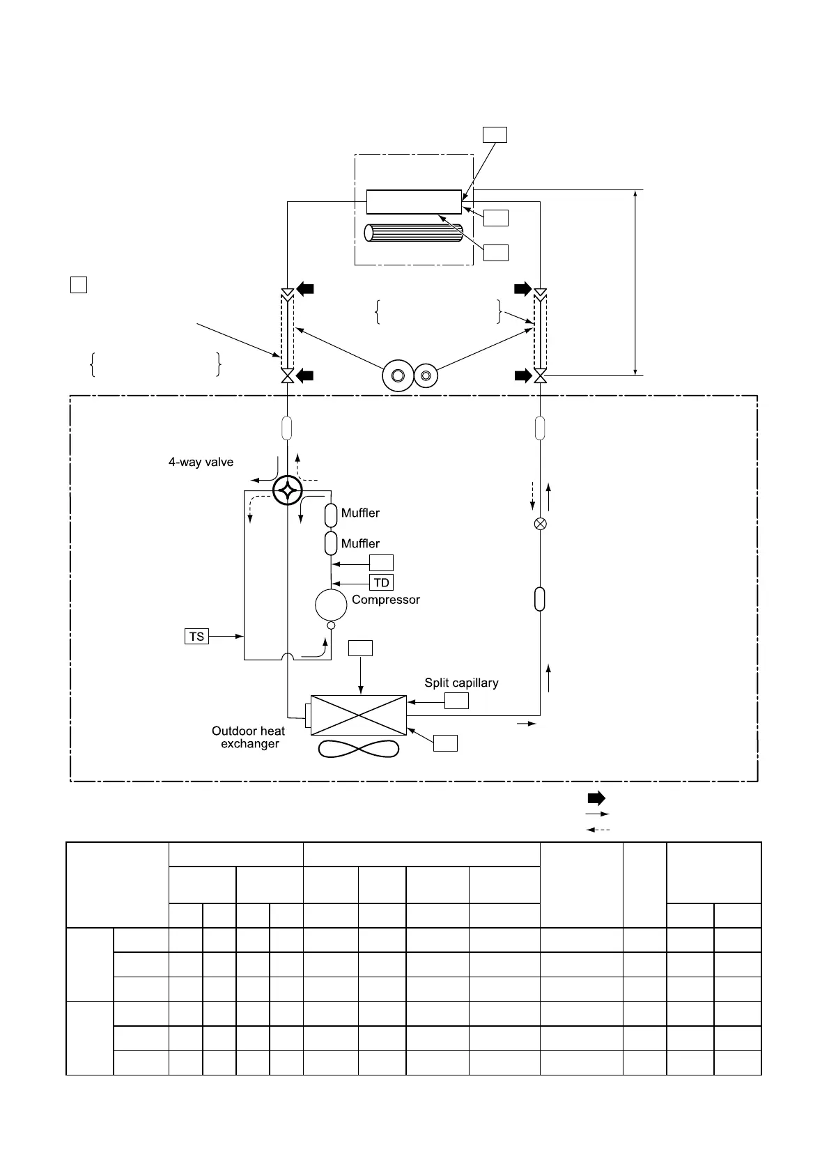
Gas leak check position
Refrigerant flow (Cooling)
Refrigerant flow (Heating)
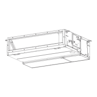
INDOOR UNIT
TCJ
Indoor heat
exchanger
Cross flow fan
Deoxidized copper pipe
Outer dia. : 9.52mm
Thickness : 0.8mm
Sectional shape
of heat insulator
Allowable height
difference : 15m
Allowable pipe length
P
Pressure measurement
Gauge attaching port
Vacuum pump connecting port
Deoxidized copper pipe
Outer dia. : 15.88mm
Thickness : 0.8mm
Pulse Modulating
valve at liquid side
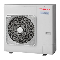
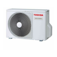
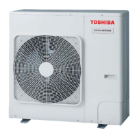
OUTDOOR UNIT
TC
TA
Strainer
Strainer
Refrigerant amount : 1.90kg
3. SYSTEMATIC REFRIGERATING CYCLE DIAGRAM
Pressure Pipe surface temperature (°C)
Compressor
drive
revolution
frequency
(rps)
Indoor
fan
Indoor/Outdoor
temp.conditions
(DB/WB) (°C)
(MPa)
(kg/cm2)
Discharge Suction
Indoor heat
exchanger
Outdoor heat
exchanger
Pd Ps Pd Ps (TD) (TS) (TC) (TE)
Indoor Outdoor
Cooling
Standard
3.14 0.96 32.0 9.8 84 13 12 37 72
HIGH 27/19 35/–
Overload
3.52 1.28 35.9 9.8 74 25 31 54 40
HIGH
32/24
46/–
Low load
2.12 0.78 21.6 8.0 60 5 4 0 54
LOW
18/15.5 -15/–
* 4 poles are provided to this compressor.
The compressor frequency (Hz) measured with a clamp meter is 2 times of revolutions (rps) of the compressor.
Heating
Standard
2.30 0.63 23.5 6.4 70 0 40 1 81
HIGH
20/- 7/6
Overload
3.31 0.98 33.7 10.0 68 13 48 14 57
HIGH
28/- 24/18
Low load
1.42 0.32 14.5 3.3 30 20 23 -17 90
LOW
0/- -15/–
Max. : 30m
Min. : 5m
High Pressure switch
NA220A1F-20
N
TO
TE
Propeller fan
TL
Strainer
 Loading...