Do you have a question about the Toshiba Strata CTX Series and is the answer not in the manual?
Explains FCC rules, registration numbers, and network connection for the Strata CTX28 system.
Details FCC compliance for RF energy and potential interference.
Covers Music-On-Hold licensing, Industry Canada certification, and REN information.
Procedures for checking system upon receipt for damage, packaging, and storage.
Lists FCC/ACTA registration numbers for Key and Multifunction systems.
Specifies input power requirements and defines minimum clearance and location conditions for the CTX28 Base KSU.
Summarizes electrical specifications (voltage, frequency, power) and environmental limits.
Details the necessity of a proper earth ground connection for the CTX28.
Explains how to test the continuity and resistance of the "wire ground" connection and summarizes wiring.
Step-by-step instructions for mounting the CTX28 Base KSU cabinet onto a wall.
Illustrates the KSU wall mounting procedure using a hard board.
Overview of installing PCBs and descriptions of their functions and purposes.
Diagram showing the interior of the CTX28 with labeled PCBs.
Instructions for setting jumpers on the GMAU motherboard for configuration.
Details the controls, switches, and indicators on the GMAU PCB.
Continues GMAU PCB description and lists GMAS sub-motherboard controls and connectors.
Step-by-step guide for installing the optional GVMU Voice Mail PCB.
Refers to GVMU programming and procedure to re-initialize it to default data.
Explains how to set language for voice mail and telephone LCD prompts.
Shows jumper settings for GVMU for different prompt languages.
Details GVMU2A strap settings and Stratagy configuration for language.
Illustrates the GVMU/GCTU PCB stopper and its placement.
Close-up view of the PCB stopper for GCTU and GVMU installation.
Explains the meaning of various LED indicators on the GVMU.
Step-by-step instructions for installing the GCTU processor PCB.
Diagram of the GCTU PCB showing connectors and indicators.
Lists controls, indicators, and connectors on the GCTU PCB.
Instructions for installing the GCDU PCB for DKT and loop start interface.
Diagram of the GCDU1A PCB with controls and connectors.
Instructions for installing the GSTU1A PCB for standard telephone interface.
Instructions for installing the GETS1A PCB for 100Base TX Ethernet.
Instructions for installing the BSIS1A PCB for RS-232 serial ports.
Instructions for installing the HPFB-6 for reserve power and battery backup.
Estimates battery backup time based on hardware configuration.
Step-by-step guide for connecting various cables and wiring for the system.
Diagram showing HPFB-6 reserve power unit installation.
Diagram illustrating standard unit wiring and AC adapter connection.
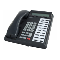
Explains compatibility and connection of Toshiba digital telephones to the CTX28.
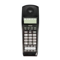
Shows AC adapter wiring procedure and illustrates the DKT3007-SD telephone.
Information on placing cabinets and maximum distance between them.
Table of maximum line lengths for different digital telephone modes.
Details loop limits for DKT3000-series telephones with PSU or battery backup.
Details where secondary protectors must be installed and provides a diagram.
Crucial advice on protecting against transient voltages with solid state protectors.
Information on MDF wiring for Amphenol connectors, CO lines, and station wiring assignments.
Diagram illustrating MDF wiring to CO lines for GMAU and GCDU.
Describes how to connect a PC to the GVMU for administration.
Diagrams for GVMU serial port and PC modem interface connections.
Explains default programming data for the CTX28 system and option units.
Table showing default programming data for digital telephones (Program 205).
Tables for default data for Programs 313, 100, and 200 (GMAU).
Tables for default data for Programs 200 (GCDU/GSTU/GVMU), 579, 580, and 218.
Tables for default data for Programs 300 and 310.
| VoIP Support | Yes |
|---|---|
| Voice Mail Integration | Yes |
| Automatic Call Distribution (ACD) | Yes |
| Caller ID | Yes |
| Call Accounting | Yes |
| Networking | Yes |
| IP Telephony | Yes |
| Power Requirements | 100-240 VAC, 50/60 Hz |
| Humidity | 10% to 90% non-condensing |
| System Type | Hybrid |
| Call Processing | Digital and IP |
| Memory | Varies by model |
| Operating Temperature | 0° to 40° C (32° to 104° F) |