E6581090
I-4
9
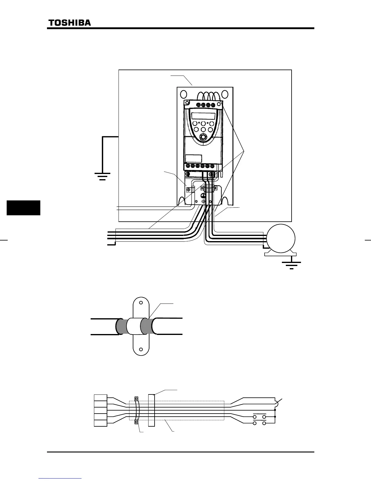
(6) Installation of the zero-phase and/or the ferrite core can also effectively reduce the radiated
noise further. (Input or/and output of inverter)
【Ex. Countermeasure - main circuit wiring】
Fig. 2
Note 1)
Process as shown below.
Shielded cable
Fig. 3
【Operating with external signals】
To ope rate with external signals, process as following figures.
Fig. 4
IM
Inverter panel
(Metal)
Separate input and
output cables.
Do not run input
cables along-side
output cables.
Do not bundle input
and output cables.
Shielded cables
Connect to the
power source
Connect to
the control
Grounding plate
EMI filter
Strip the coating of the cable and fix the shielded part
to the metal plate using a metal fitting.
P5
VI/S3
CC
F
R
Control
circuit
terminal
Ferrite core 1
Shielded cable
Potentiometer
Forward
Reverse
NOTE1)

 Loading...


