E6581090
B-8
2
FLA
FLB
FLC
CC
CC
CC
S2
R
S1
F
P5
FM/OUT
VI/S3
P15
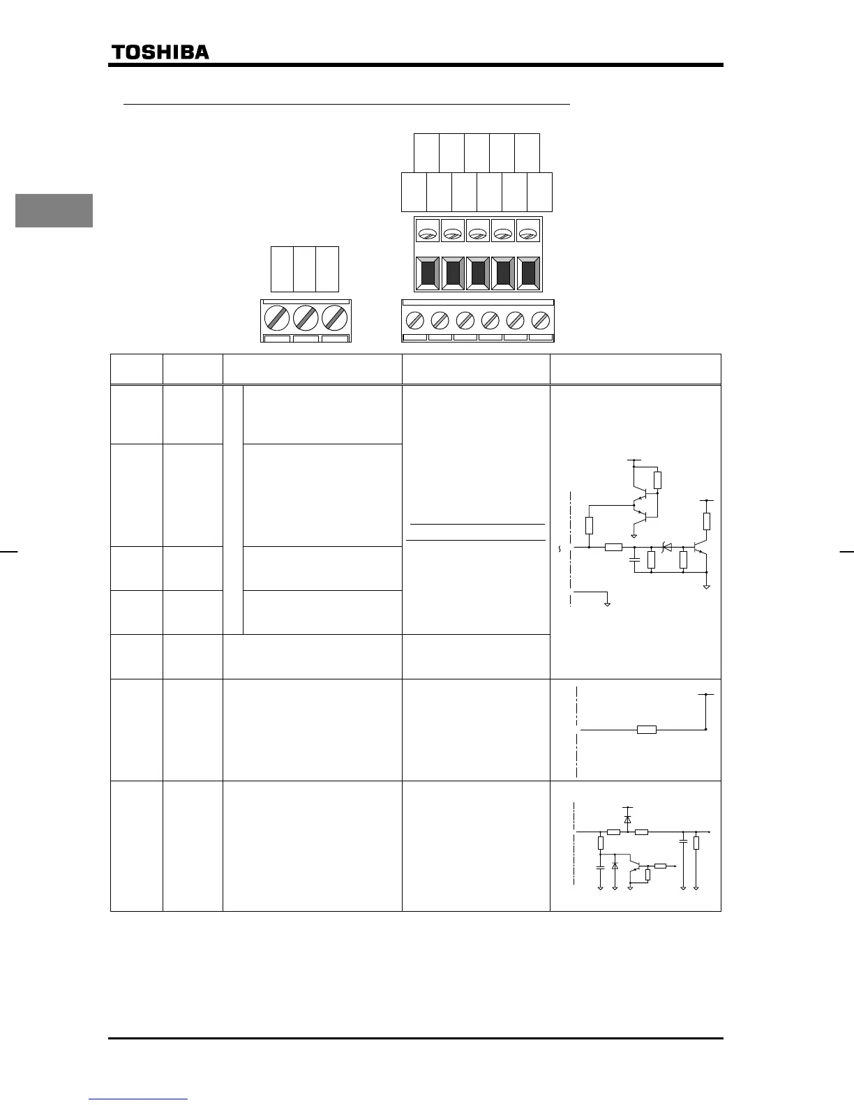
2.3.2 Control circuit terminals (sink logic (common: CC))
The control circuit terminal board is the same for all models.
Term i na
l symbol
Input/
output
Function Specifications Inverter internal circuit
FInput
Shorting across F-CC
causes forward rotation;
open causes slowdown and
stop. (If ST is always ON)
RInput
Shorting across R-CC
causes reverse rotation;
open causes slowdown and
stop. (If ST is always ON)
Shorting across R-CC/F-
CC causes reverse
rotation.
S1 Input
Shorting across S1-CC
causes preset speed
operation.
S2 Input
Multifunction programmable contact input
Shorting across S2-CC
causes preset speed
operation.
Dry contact input
15Vdc - 5mA or less
*Sink/source selectable
by changing a parameter
CC
Common
to input/
output
Control circuit’s equipotential
terminal.
P5 Output
Power output for analog input
setting.
5Vdc
(permissible load current:
10mAdc)
VI/S3 Input
Multifunction programmable
analog input.
Standard default setting:
Analog input 0-10Vdc and
frequency 0-80Hz.
Possible to use as analog input
(4 (0)-20mAdc) or contact input
(programmable contact input)
by changing a parameter.
10Vdc:
(internal impedance:
42kΩ)
4-20mA:
(internal impedance:
250Ω)
◎
4.7K
3.7K
+5V
22K 1K
0.047μ
+15V
F
S
2
~
◎CC
◎
249
+5V
20K 2K
0.047μ
VI/S3
0.047μ
20K
◎
100
P5
+5V

 Loading...


