E6581913
55
Output data on the terminal board (FA50)
The output data on the terminal board can be directly controlled with the computer.
To use this function, select functions from 92 to 95 in advance for the output terminal selection
parameters f130, f131, f132. If bit 0 through bit1 of the data (FA50) is set with the
computer, the specified data (0 or 1) can be output to the selected output terminal.
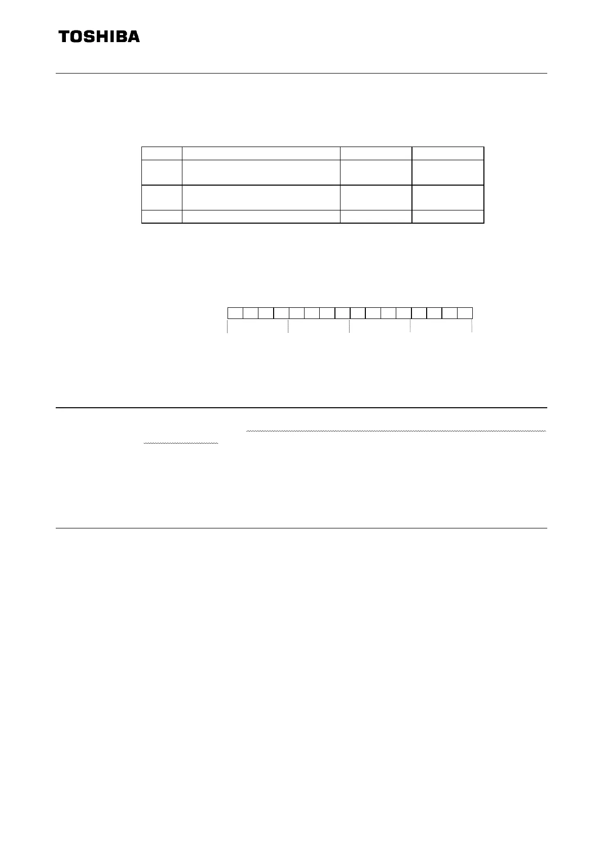
Data composition of output data on the terminal board (FA50)
Bit Output terminal function 0 1
0 Specified data output 1
(Output terminal no.: 92, 93)
OFF ON
1 Specified data output 2
(Output terminal no.: 94, 95)
OFF ON
2-15 (Reserved)
- -
Note: Set 0 to reserved bit
Example of use: To control only the RY-RC terminal with the computer
To turn on the RY terminal, set the output terminal selection 1A parameter (f130) to 92
(Designated data output 1) and set 0001H to FA50.
BIT15 BIT0
0 0000000000000 0 1
FM analog output (FA51)
The FM analog output terminal on each inverter can be directly controlled with the computer.
To use this function, set the FM terminal meter selection parameter (fmsl) to 18 (RS485 com-
munication data).
This makes it possible to send out the data specified as FM analog output (FA51) through the FM
analog output terminal. Data can be adjusted in a range of 0 to 100.0 (resolution of 10 bits).
For details, refer to “Meter setting and adjustment” of the inverter’s instruction manual.
Information for reset or not (FA87)
FA87 sets to ‘1’ by user-communication. If the inverter reset, FA80 set to ‘0’ by the inverter.
FA50:
0
0
0
1
Phone: 800.894.0412 - Fax: 888.723.4773 - Web: www.clrwtr.com - Email: info@clrwtr.com

 Loading...


