4
Heating Operation
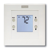
1. Press MODE button until HEAT is displayed.
2. Press UP button until LCD readout reads 3_F/2_C above
room temperature. Press UP and FAN buttons simultane-
ously to defeat timers. Heating system should begin to oper-
ate immediately.
3. For HP applications only, press MODE button until EMHT
(emergency heat) appears. Press UP and FAN buttons si-
multaneously to defeat timers. Emergency heating (W is
ON, Y is OFF) should begin immediately.
Cooling Operation
1. Press MODE button until COOL is displayed.
2. Press DOWN button until LCD readout reads 3_F/2_Cbe-
low room temperature. Press UP and FAN buttons simulta-
neously to defeat timers. Cooling system should begin to
operate immediately.
Table 1 shows the thermostat outputs for each available stage of
heating or cooling. It may be useful in checkout or
troubleshooting.
Table 1 – Outputs
EQUIPMENT
CONFIGURATION OP-
TION #1
COOL
STAGE 1
HEAT
STAGE 1
HEAT
STAGE 2
EM HEAT
AC, PC Y, G W --- --- --- ---
HP, PH
RVS = C
Y, G , O / B Y, G Y, G , W W
HP, PH
RVS = H
Y, G Y, G , O / B Y, G , W, O / B W
WIRING DIAGRAMS
A06566
Fig. 1 -- A/C Thermostat Typical Installation
A06567
Fig. 2 -- HP Thermostat Typical Installation
Replacement Components, Carrier Corporation www.totaline.com Edition Date: 02/14 U.S. Export Classification: EAR99.
Manufacturer reserves the right to change, at any time, specifications and designs without notice and without obligations.
Catalog No: RCIIP710U---21PHP---03
Replaces: RCIIP710U--- 21PHP--- 02
 Loading...
