D
O
N
O
T
U
S
E
P
E
T
R
O
L
E
U
M
-
B
A
S
E
D
S
E
A
L
A
N
T
S
A
T
T
E
N
T
I
O
N
!
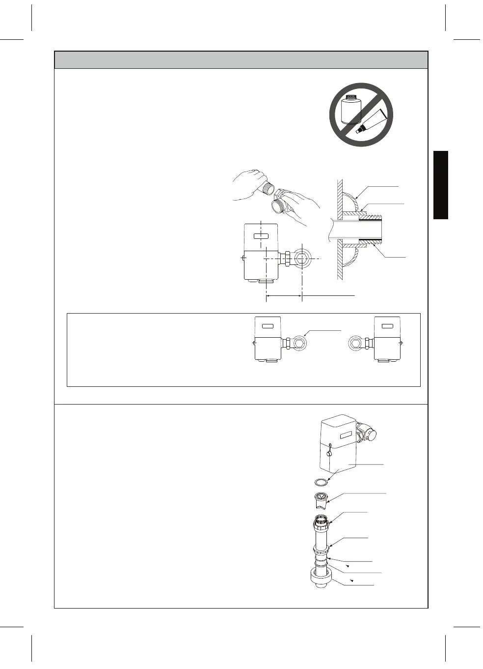
INSTALLATION PROCEDURE
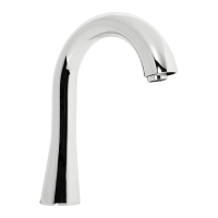
Escutcheon
Covering tube
Adapter
Min.4-1/4"(107mm)
Max.5-1/4"(133mm)
For sweat solder
Vacuum breaker
Tube nut
Spud nut
Slip gasket
Rubber gasket
Escutcheon
1. Install the control stop using an
appropriate size escutcheon and a
sweat solder
adapter kit, if applicable.
Thread sealing
compounds should be
used on male NPT threads only.
The distance from center of the control
stop to center of the Flush Valve
should fall within 4-1/4" to
5-1/4"(107mm to 133mm).
For use with a left water supply, attach
the sensor top cover in the opposite
direction so that the sensor will be at
the front.
2. Determine the length of vacuum
breaker tube to join the Flush Valve
and fixture spud. If required, cut the
vacuum breaker tube to the proper
length.
3. Assemble the spud nut assembly to
the fixture spud. Hand tighten spud
nut to fixture.
NOTE: For retrofit installation, remove the old Flush Valve
after shutting off the control stop.
NOTE: For reclaimed water, do not use standard vacuum
breaker or control stop.
NOTE: Do not use petroleum based products or pipe
sealants.
Control stop
Right Water Supply Left Water Supply
ENGLISH
7
Friction washer
 Loading...