Network Topology
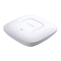
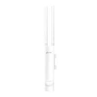
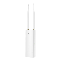
Hardware Overview
1
Installation Steps
Quick Installation Guide
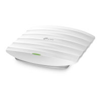
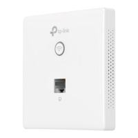
EAP115-Wall
300Mbps Wireless N Wall-Plate Access Point
3
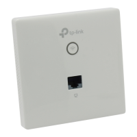
Front Panel
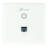
Rear Panel
LAN Port
EAPEAPEAP
PC
PoE Switch
Router
Internet
Clients
EAP Controller
RESET
LED
Pre-Installation Checklist
2
UPLINK+PoE Port
Connected to a PSE (Power Sourcing Equipment), such as a PoE switch, for
both data transmission and Power.
LED/Wi-Fi Button
When the EAP is working in Standalone Mode and enabled with Wi-Fi
Control, press the button to turn on/o both of the Wi-Fi and LED. In other
cases, press the button to turn on/o the LED only.
LAN Port
A wired device can be connected to the LAN port via an Ethernet cable
and access the network.
RESET
With the EAP powered on, press and hold the button for about 5 seconds
until the LED ashes. The EAP will restore to factory default settings.
LED Indicator
On: Working normally/Initializing.
O: Working abnormally/Power o/LED is turned o.
Flashing:
Initialization: The LED ashes twice after initialization is complete.
Upgrade: The LED ashes once per second while upgrading.
Reset: The LED ashes ve times in quick session during the reset. The
EAP will then reboot.
The EAP115-Wall can only be powered by a PSE device, such as a PoE switch.
Connect the PoE switch to the UPLINK+PoE port with an Ethernet cable.
A DHCP server (typically a router) with DHCP function enabled is required to
assign IP addresses to the EAPs and clients in your local network.
Before installation, be sure that you have the following items:
1. A pre-installed wall junction box
2. An RJ45 plug
3. A triangular screwdriver
EAP115-Wall can be mounted into either an 86mm wall junction box or a
standard EU wall junction box. The junction box should be pre-installed with
a running-in-wall Ethernet cable connected to a PoE switch.
LED/Wi-Fi Button
Standard EU wall junction box
86mm wall junction box
4. A Phillips screwdriver
5. A PoE switch
1. Detach the faceplate of the junction box with a Phillips screwdriver
(demonstrated with an 86mm wall junction box).