Typical Network Topology
Hardware Installation
2
Option 1: Ceiling Mounting
5
Feed the Ethernet cable through the hole
and set the ceiling tile back into place.
Connect the Ethernet cable to the
ETHERNET port.
2
Place the mounting bracket in the center
of the ceiling tile. Mark three positions for
the screw holes and a position for the
Ethernet cable hole.
Drill three 4mm holes for the screws and a
25mm hole for the Ethernet cable at the
marked positions.
1
Remove the ceiling tile.
3
Secure the mounting bracket to the
ceiling tile using three M3x30 pan-head
screws, washers and wing nuts, as shown
on the left.
EAPEAPEAP
Management Host
A DHCP server (typically a router) is required to assign IP addresses to the EAPs and clients in your local network.
The management host can be in the same or different network segment with the EAPs.
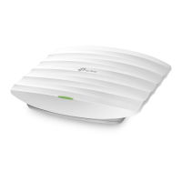
Option 1: Ceiling Mounting
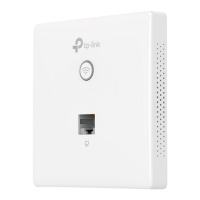
Option 2: Wall Mounting
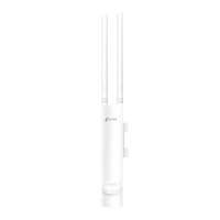
The EAP can be ceiling-mounted or wall-mounted.
Hole for Ethernet cable
X3
Switch
Router
Internet
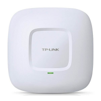
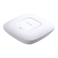
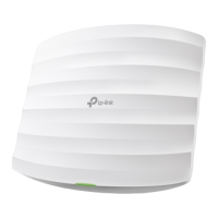
Quick Installation Guide
EAP115
Wireless N Access Point
LED Indication
The device is working properly.
Solid green
System errors. RAM, Flash,
Ethernet, WLAN or firmware may
be malfunctioning.
Flashing red
The device is being reset to its
factory default settings.
Double-flashing red, green, yellow
Firmware update is in progress. Do not
disconnect or power o the device.
Flashing yellow
Clients
Wing Nuts (Qty.3)Washers(Qty.3)
M3×30 Pan-head Screws (Qty.3)
1
4
Attach the EAP to the mounting bracket by
aligning the arrow mark on the EAP with
the arrow mark on the mounting bracket,
then rotate the EAP until it locks into place,
as shown on the left.
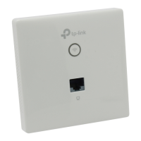
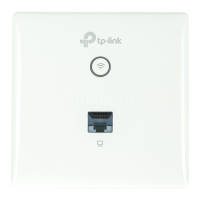
EAP Controller
Interface Panel
RESET
With the device powered on, press and hold the button for about 8 seconds until the LED
flashes red, then release the button. The device will restore to factory default settings.
RESET ETHERNET POWER
The port is used to connect to a router or a switch to transmit data or to a PSE (Power
Sourcing Equipment), such as a PoE switch, for both data transmission and Power over
Ethernet (PoE) through Ethernet cabling.
ETHERNET
This port is used to connect to the provided power adapter to power the EAP. The other end
of the power adapter connects to a standard electrical wall outlet.
POWER