EasyManua.ls Logo

TP-Link Omada SG2218P - User Manual

TP-Link Omada SG2218P
20 pages
Print Icon
To Next Page IconTo Next Page
Loading...
Business Networking Solution
Installation Guide
Omada Smart Switch
Question and Answer IconNeed help?

Do you have a question about the TP-Link Omada SG2218P and is the answer not in the manual?

Overview

The TP-Link Omada Smart Switch is a business networking solution designed for robust and scalable network management. It offers advanced L2 management features, including comprehensive QoS, IGMP snooping/filtering, and VLAN capabilities, making it suitable for diverse workgroup and department needs. The switch integrates seamlessly into Omada SDN (Software Defined Networking) for centralized cloud management, enhancing efficiency and simplifying network administration.

Function Description

The Omada Smart Switch provides wire-speed performance and abundant L2 management features, catering to various service features and multiple powerful functions for high security. It supports the EAP-standardized framework and smart configuration capacity, offering flexible solutions for a variable scope of networks. The switch is designed to optimize voice and video applications, and its link aggregation capabilities increase aggregated bandwidth. It integrates multiple functions with excellent performance, making it suitable for managing complex network environments and meeting the needs of users demanding higher networking performance.

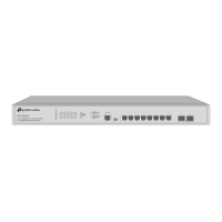
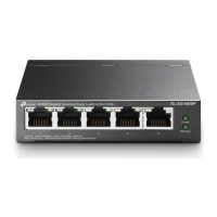
Specific models like the SG2210MP, SG2218P, SG2428P, and SL2428P are Power Sourcing Equipment (PSE), meaning they can automatically detect and supply power to powered devices (PDs) compliant with IEEE 802.3af and IEEE 802.3at. This PoE functionality simplifies deployment for devices like IP cameras, wireless LAN access points, and IP phones, eliminating the need for separate power cables.

The switch can operate in two modes: Standalone Mode and Controller Mode. In Standalone Mode, the switch is configured and managed individually via a web-based GUI or CLI. In Controller Mode, the switch is managed by an Omada Hardware Controller (OC200/OC300) or Omada Software Controller, allowing for centralized management of multiple Omada devices. This centralized approach simplifies configuration, monitoring, and troubleshooting across the entire network.

Important Technical Specifications

The Omada Smart Switch series adheres to various IEEE standards, including IEEE 802.3i, IEEE 802.3u, IEEE 802.3ab, IEEE 802.3ad, IEEE 802.3z, IEEE 802.3x, IEEE 802.1p, IEEE 802.1q, IEEE 802.1x, IEEE 802.1d, IEEE 802.1s, IEEE 802.1w, and IEEE 802.3af/at (for PoE models).

Transmission Medium:

  • 10Base-T: UTP/STP of Cat. 3 or above
  • 100Base-TX: UTP/STP of Cat. 5 or above
  • 100Base-FX/LX/BX10: MMF or SMF SFP Module (For SG2210MP/SG2428P)
  • 1000Base-T: 4-pair UTP (≤ 100 m) of Cat. 5e, and Cat. 6 or above
  • 1000Base-SX/LX/LX10/BX10: MMF or SMF SFP Module

LEDs:

The switches feature various LEDs to indicate status:

  • PWR: Power status. On indicates power is supplied, Off indicates no power or power supply abnormality, and Flashing indicates power supply abnormality.
  • SYS: System status. On or Off indicates the switch works properly, Flashing indicates the switch works improperly.
  • Link/Act: Link/Activity status. On indicates a device is connected but no activity, Flashing indicates data is being transmitted or received, and Off indicates no device is connected to the corresponding port.
  • 1000Mbps: Speed status. On indicates running at 1000 Mbps, Off indicates running at 10/100 Mbps or no device is linked.
  • 10/100M or PoE Speed or PoE (When the Speed LED is on): Indicates port speed (10/100 Mbps) or PoE status. Green On indicates 100 Mbps, Green Flashing indicates 100 Mbps transmitting/receiving data. Yellow On indicates 10 Mbps, Yellow Flashing indicates 10 Mbps transmitting/receiving data. Off indicates no device or link. For PoE, Green On indicates power supply is normal, Green Flashing indicates power supply exceeds maximum power, Yellow On indicates overload or short circuit, Yellow Flashing indicates power-on self-test failed.
  • SFP1, SFP2: Speed status for SFP ports. Green On indicates 1000 Mbps, Green Flashing indicates 1000 Mbps transmitting/receiving data. Yellow On indicates 100Base-X, Yellow Flashing indicates 100Base-X transmitting/receiving data. Off indicates no device or link.

Environmental Specifications:

  • Operating Temperature: 0°C to 50°C (32°F to 122°F) for SG2210MP/SG2218P/SG2428P/SL2428P; 0°C to 40°C (32°F to 104°F) for other switches.
  • Storage Temperature: -40°C to 70°C (-40°F to 158°F).
  • Operating Humidity: 10% to 90% RH Non-condensing.
  • Storage Humidity: 5% to 90% RH Non-condensing.

Port Features:

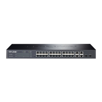
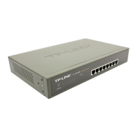
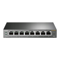
The switches offer various port configurations, including 100M/1000M/10Gbps RJ45 ports, 10/100/1000 Mbps RJ45 ports, 10/100 Mbps RJ45 ports, SFP Slots, and SFP+ Slots, depending on the specific model. For instance, the SG2210MP has 8 10/100/1000 Mbps RJ45 PoE ports and 2 SFP slots. The SG2428P has 24 10/100/1000 Mbps RJ45 PoE ports and 4 SFP+ slots.

Usage Features

Installation: The switch supports both desktop and rack installation. For desktop installation, it should be placed on a flat surface with sufficient space for ventilation. For rack installation, it can be mounted in an EIA standard 19-inch rack using the provided rack-mounting brackets. Proper air circulation is crucial, requiring at least 5 to 10 cm of space around the device.

Connection:

  • Ethernet Port: Connect an Ethernet port of the switch to a computer using an RJ45 cable.
  • SFP Slot: Insert an SFP module into the SFP slot for fiber optic connections.
  • Power On: Connect the provided power cord into the power socket of the device and plug the positive connector into a power outlet. The device performs a Power-On Self-Test (POST) upon powering on, with LED indicators responding in the following order: PWR LED lights on, SYS LED and LED indicators of all ports keep off. Then, after about one minute, all LED indicators turn green, then the FAN indicator and LED indicators of all ports turn yellow momentarily. Subsequently, all LED indicators except the PWR LED turn off. For other switches, after about one minute, the SYS LED and LED indicators of all ports will flash momentarily and then turn off. A successful initialization is indicated by the SYS LED flashing several seconds later.

Configuration:

  • Standalone Mode: Configure and manage the switch individually via its web-based GUI. To access the management page, the switch and computer must be in the same subnet. The default IP address is 192.168.0.1.
  • Controller Mode: Manage the switch centrally using an Omada Hardware Controller (OC200/OC300) or Omada Software Controller. This mode is ideal for large-scale networks with multiple devices. The controller discovers and adopts the switch, allowing for unified configuration and monitoring.

Omada SDN Integration: The switch is a key component of the Omada SDN solution, which provides centralized cloud management. This allows users to manage their entire network from a single interface, including access points, switches, and gateways. The Omada app provides convenient remote management via a smartphone or tablet.

PoE Functionality: For PoE-enabled models, the switch automatically detects and powers connected PDs, simplifying network deployment and reducing cabling requirements. This is particularly useful for IP surveillance systems, VoIP phones, and wireless access points.

Maintenance Features

Safety Precautions:

  • Always keep the power off during installation.
  • Wear an ESD-preventive wrist strap to prevent electrostatic discharge.
  • Use only the power cord provided with the switch.
  • Ensure the switch is installed in a well-ventilated environment.
  • Do not open or remove the cover of the switch.
  • Clean the device with a soft, dry cloth; do not use liquid cleaning methods.
  • Place the device with its bottom surface downward.

Electromagnetic Interference: The device is designed to minimize electromagnetic interference. However, to ensure optimal performance, avoid placing the switch near strong electromagnetic sources. Use shielded cables and ensure proper grounding.

Lightning Protection: The switch is designed with surge protective devices (SPD) to mitigate damage from lightning strikes. For detailed lightning protection measures, refer to the TP-Link website for relevant guides. It is recommended to use the provided grounding terminal to connect the switch to a protective earth ground.

Troubleshooting: The manual provides troubleshooting steps for common issues, such as:

  • Forgot username and password: Press the Reset button for at least 5 seconds to restore factory default settings.
  • PWR/Power LED abnormal: Check the power supply connection and ensure the power voltage is within the required range.
  • Cannot access web management page: Verify Ethernet cable connection, check the IP address of the PC, and ensure the switch is not in a factory default state with an IP address of 192.168.0.1.

Firmware Updates: For optimal performance and security, it is recommended to regularly check for and install firmware updates from the official TP-Link website. The user guide and CLI reference guide, available on the download center, provide detailed instructions for managing and maintaining the device.

Community Support: TP-Link offers a community forum for users to ask questions, find answers, and communicate with other users and engineers. Technical support, user guides, and other information are also available on the TP-Link support website.

TP-Link Omada SG2218P Specifications

General IconGeneral
BrandTP-Link
ModelOmada SG2218P
CategorySwitch
LanguageEnglish

Related product manuals