Omada L2+/Stackable Lite L3 Managed Switch
24 Connection
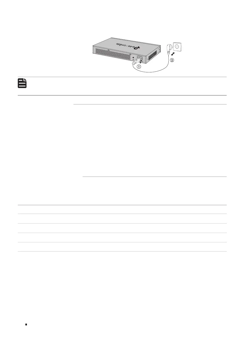
Figure 3-5 Connecting to Power Supply
Note:
■
The figure is to illustrate the application and principle. The provided plug and the socket in
your region may differ from the figures above.
3.6 Initialization
After the device is powered on, it begins the Power-On Self-Test. A series of tests run automatically
to ensure the device functions properly. During this time, its LED indicators will respond in the
following order:
1. The PWR LED indicator lights on all the time. The SYS LED and the LED indicators of all the ports
keep off.
2. After about one minute, the SYS LED and LED indicators of all the ports will flash momentarily and
then turn off.
3. Several seconds later, the SYS LED indicator will flash, which represents a successful initialization.
3.7 Stack Topology
With stackable design, the Lite L3 switches can be stacked into one stack topology for higher
reliability, larger bandwidth, and simpler networking. To build the stack topology, you need to prepare
2-4 switches and enough 10G SFP+ modules/cables. For more details, see the table below:
Switch Compatible Model(s) Quantity
SG5428X SG5428X, SG5428XMPP, SG5452X, SG5452XMPP 2-4
SG5428XMPP SG5428X, SG5428XMPP, SG5452X, SG5452XMPP 2-4
SG5452X SG5428X, SG5428XMPP, SG5452X, SG5452XMPP 2-4
SG5452XMPP SG5428X, SG5428XMPP, SG5452X, SG5452XMPP 2-4
There are three stack topology structures for different scenarios, please build the proper topology
according to your needs:
1. Chain Topology: Chain topology is relatively simple and does not require cable connection
between the first and last unit. It is suitable for long-distance stacking, but its reliability is relatively
low.