Do you have a question about the TP-Link TL-SG1024D and is the answer not in the manual?
Details the switch's purpose, performance, and key technical features.
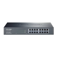
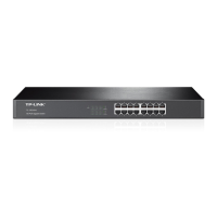
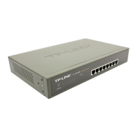
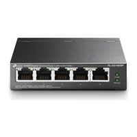
Illustrates front and rear panels, ports, and LED indicators for various switch models.
Ensures all items are present and outlines crucial safety rules for device installation and handling.
Details environmental conditions (temp, humidity, clearness, EMI) and necessary installation tools.
Provides step-by-step instructions for desktop and rack mounting the switch.
Guidelines for reasonable cabling systems to minimize lightning-induced damage in different environments.
Explains methods for connecting the device to ground and achieving equipotential bonding.
Information on using power and signal lightning arresters for comprehensive protection.
Instructions for connecting the switch via Ethernet port and verifying the installation steps.
Steps for powering on the switch and understanding the Power-On Self-Test (POST) indicators.
Diagnoses and checks for issues when the Power LED indicator is not illuminated.
Troubleshooting steps for when the Link/Act LED does not activate with a connected device.
| Jumbo frames | 10000 |
|---|---|
| Forwarding rate | 35.7 Mpps |
| MAC address table | 8000 entries |
| Jumbo frames support | Yes |
| Maximum data transfer rate | 1 Gbit/s |
| Supported data transfer rates | 10/100/100 Mbps |
| 10G support | No |
| Networking standards | IEEE 802.3ab, IEEE 802.3u, IEEE 802.3x |
| Cable types supported | Cat3, Cat4, Cat5, Cat5e |
| Dimensions (WxDxH) | 294 x 180 x 44 mm |
| Power requirements | 100 - 240V, 50/60Hz |
| Networking features | Gigabit Ethernet |
| Connectivity technology | Wired |
| Switch type | Unmanaged |
| Supported network protocols | CSMA/CD, TCP/IP |
| Power connector | DC-in jack |
| Installed SFP+ modules quantity | 0 |
| Basic switching RJ-45 Ethernet ports type | Gigabit Ethernet (10/100/1000) |
| Basic switching RJ-45 Ethernet ports quantity | 24 |
| Certification | FCC, CE, RoHS |
| Product color | Gray |
| Power source | AC |
| AC input voltage | 100 - 240 V |
| AC input frequency | 50 - 60 Hz |
| Power consumption (max) | 13.62 W |
| Heat dissipation | 46.44 BTU/h |
| Storage temperature (T-T) | -40 - 70 °C |
| Operating temperature (T-T) | 0 - 40 °C |
| Storage relative humidity (H-H) | 5 - 90 % |
| Operating relative humidity (H-H) | 10 - 90 % |
| Package type | Box |
| Package depth | 400 mm |
| Package width | 250 mm |
| Package height | 80 mm |
| Package weight | 1950 g |
| Harmonized System (HS) code | 85176990 |
| Depth | 180 mm |
|---|---|
| Width | 294 mm |
| Height | 44 mm |