Do you have a question about the TP-Link TL-SG2008P and is the answer not in the manual?
Details PoE Status LED behavior for ports, indicating power provision or fault conditions.
Explains the POE MAX LED for TL-SG2008P/TL-SG2210P, indicating total power supply status.
Configure and manage the switch individually via its management page.
Configure and manage network devices centrally using a controller.
Important safety guidelines for device operation, maintenance, and environment.
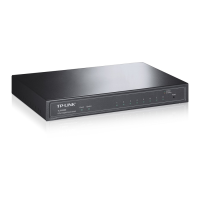
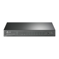
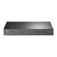
The TP-Link JetStream Gigabit Smart PoE+ Switch is a network device designed for efficient data transmission and Power over Ethernet (PoE) capabilities, suitable for both standalone and centrally managed network environments. It facilitates the connection and power supply to various PoE-compatible devices such as IP cameras, access points, and IP phones, alongside standard network clients like PCs.
The primary function of this switch is to provide high-speed Gigabit Ethernet connectivity and Power over Ethernet (PoE+) to connected devices. It acts as a central hub for network traffic, forwarding data packets between connected clients at speeds of 10/100/1000 Mbps. The PoE+ capability allows the switch to deliver both data and electrical power over a single Ethernet cable, simplifying network deployment by eliminating the need for separate power outlets for PoE-enabled devices. This is particularly beneficial for devices located in areas where power access is limited or inconvenient. The switch supports the PoE+ standard, providing up to 30 W of power per port, with a total power budget that varies by model (e.g., 62 W for TL-SG2008P and 61 W for TL-SG2210P). This ensures compatibility with a wide range of power-hungry PoE devices.
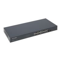
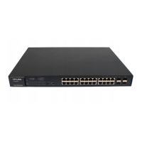
The switch also includes SFP slots (for models like TL-SG2210P), which enable fiber optic connections for long-distance data transmission, extending the network's reach beyond the limitations of copper cabling. This feature is crucial for connecting to backbone networks or other remote network segments.
The switch offers flexible configuration and management options, catering to different network scales and administrative preferences. It supports two main modes of operation: Standalone Mode and Controller Mode.
In Standalone Mode, the switch can be configured and managed individually through a web-based graphical user interface (GUI). Users can access the management page by typing the switch's IP address into a web browser. If the switch obtains an IP address from a DHCP server, its address can be found on the DHCP server's client list. Otherwise, a default IP address (e.g., 192.168.0.1) can be used. Upon initial login, users are prompted to change the default password for enhanced security. The GUI provides access to various functions, allowing users to customize network settings, monitor port status, and manage PoE allocations. This mode is ideal for smaller networks or situations where centralized management is not required.
For larger and more complex networks, the Controller Mode offers centralized management of multiple network devices, including access points, switches, and gateways. This mode can be implemented using either an Omada Hardware Controller (OC200/OC300) or an Omada Software Controller running on a PC.
With an Omada Hardware Controller, the device provides a dedicated platform for managing the network without the need for a continuously running PC. The hardware controller obtains an IP address from the network's DHCP server and can be accessed via a web browser. Once connected, users can follow a quick setup wizard to configure the network. Remote management is also possible through the Omada Cloud Service, requiring the controller and the managing PC to have internet access and Cloud Access enabled on the controller.
The Omada Software Controller runs on a Windows or Linux PC and offers similar centralized management capabilities. After downloading and installing the software, users can launch the controller, which automatically opens its web page. Like the hardware controller, it allows for quick setup and remote management via the Omada Cloud Service, provided Cloud Access is enabled and the controller is bound to a TP-Link ID.
Both controller modes also support management via the Omada App on mobile devices (available on App Store and Google Play). The app allows for both local and remote management. For local management, the mobile device can connect to an EAP's default SSID, and then the app can be used to add and configure the controller. For remote management, the app connects to the Omada Cloud Service, allowing users to manage controllers bound to their TP-Link ID from anywhere with internet access.
The switch's LED indicators provide visual feedback on its operational status. The "Power" LED indicates whether the device is powered on. The "System" LED flashes when the system is running normally. "Link/Act" LEDs for each port show connection status (On for active link, Flashing for data transmission) and speed (Green for 1000 Mbps, Yellow for 10/100 Mbps). "PoE Status" LEDs indicate when PoE power is being provided, flash for issues like overload or non-standard devices, and are off when no PoE power is supplied. A "PoE MAX" LED indicates the total power supply status relative to the maximum budget.
Maintaining the TP-Link JetStream Gigabit Smart PoE+ Switch involves ensuring its optimal performance and longevity. The web-based management interface in Standalone Mode and the Omada Controller interfaces in Controller Mode provide tools for monitoring the switch's health and performance. Users can view port status, PoE usage, and system logs to identify and troubleshoot potential issues.
Regular firmware updates are crucial for maintaining security and accessing new features. These updates can typically be downloaded from the TP-Link support website and applied through the management interface.
For security, it is essential to change default login credentials immediately after initial setup and to use strong, unique passwords. In Controller Mode, binding the controller to a TP-Link ID and enabling Cloud Access requires secure credentials to protect remote management capabilities.
In case of issues, the device manual and the TP-Link support website offer comprehensive troubleshooting guides, user manuals, and CLI guides. The TP-Link Community forum also provides a platform for users to ask questions, find answers, and interact with other users and engineers.
Physical maintenance involves keeping the device in a suitable environment, away from water, fire, humidity, or extreme temperatures. The device should not be disassembled, repaired, or modified by unauthorized personnel. Using only recommended chargers and power cords is important to prevent damage. The adapter should be installed near the equipment for easy accessibility, and the power supply cord's plug serves as the disconnect device, so the socket-outlet should also be easily accessible. The device should be placed with its bottom surface downward to ensure proper ventilation and stability.
| Ports | 8 |
|---|---|
| PoE Ports | 8 |
| Total PoE Power Budget | 62 W |
| Switching Capacity | 16 Gbps |
| Forwarding Rate | 11.9 Mpps |
| Interface | 8 x 10/100/1000 Mbps RJ45 Ports |
| Jumbo Frame | 9 KB |
| MAC Address Table | 8K |
| Power Input | 100-240VAC, 50/60Hz |
| Operating Humidity | 10% to 90% non-condensing |
| Storage Humidity | 5% to 90% non-condensing |
| Management | CLI |
| Standards and Protocols | IEEE 802.3af, IEEE 802.3at |
| VLAN | 4K |
| Operating Temperature | 0°C to 40°C (32°F to 104°F) |
| Storage Temperature | -40°C to 70°C (-40°F to 158°F) |
| Layer | L2 |