Do you have a question about the TP-Link TL-SL1226 and is the answer not in the manual?
| MAC address table | 8000 entries |
|---|---|
| Maximum data transfer rate | 1 Gbit/s |
| Supported data transfer rates | 10/100 Mbps |
| Full duplex | Yes |
| Switch type | Unmanaged |
| Switch layer | - |
| Supported network protocols | CSMA/CD, TCP/IP |
| Basic switching RJ-45 Ethernet ports quantity | 26 |
| Size (imperial) | 19 \ |
| Dimensions (WxDxH) | 440 x 180 x 44 mm |
| Connectivity technology | Wired |
| Dimensions (W x D x H) (imperial) | 17.3 x 7.1 x 1.7 \ |
| Stackable | No |
| Certification | CE, FCC |
| Product color | Black |
| Power source | 100-240VAC, 50/60Hz |
| Power consumption (typical) | 18 W |
| Storage temperature (T-T) | -40 - 70 °C |
| Operating temperature (T-T) | 0 - 40 °C |
| Storage relative humidity (H-H) | 5 - 90 % |
| Operating relative humidity (H-H) | 10 - 90 % |
Warns that the Class A product may cause radio interference in domestic environments.
Provides cautions regarding water exposure and lightning during electrical storms.
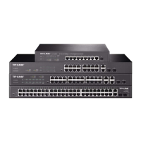
Describes the switch's high-performance, low-cost, and easy-to-use features for network upgrades.
Lists key technical specifications and capabilities of the TP-LINK Gigabit Switches.
Instructions for placing the switch on a flat surface using rubber footpads.
Steps for installing the switch into a standard 19-inch equipment rack.
Details on how to install and configure an SFP module for specific models.
Explains the procedure for powering on the switch and expected LED indicator behavior.
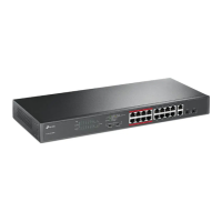
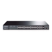
Details the layout and function of LED indicators, RJ-45 ports, and SFP module on the front.
Describes the power receptacle and other connections on the rear of the switch.