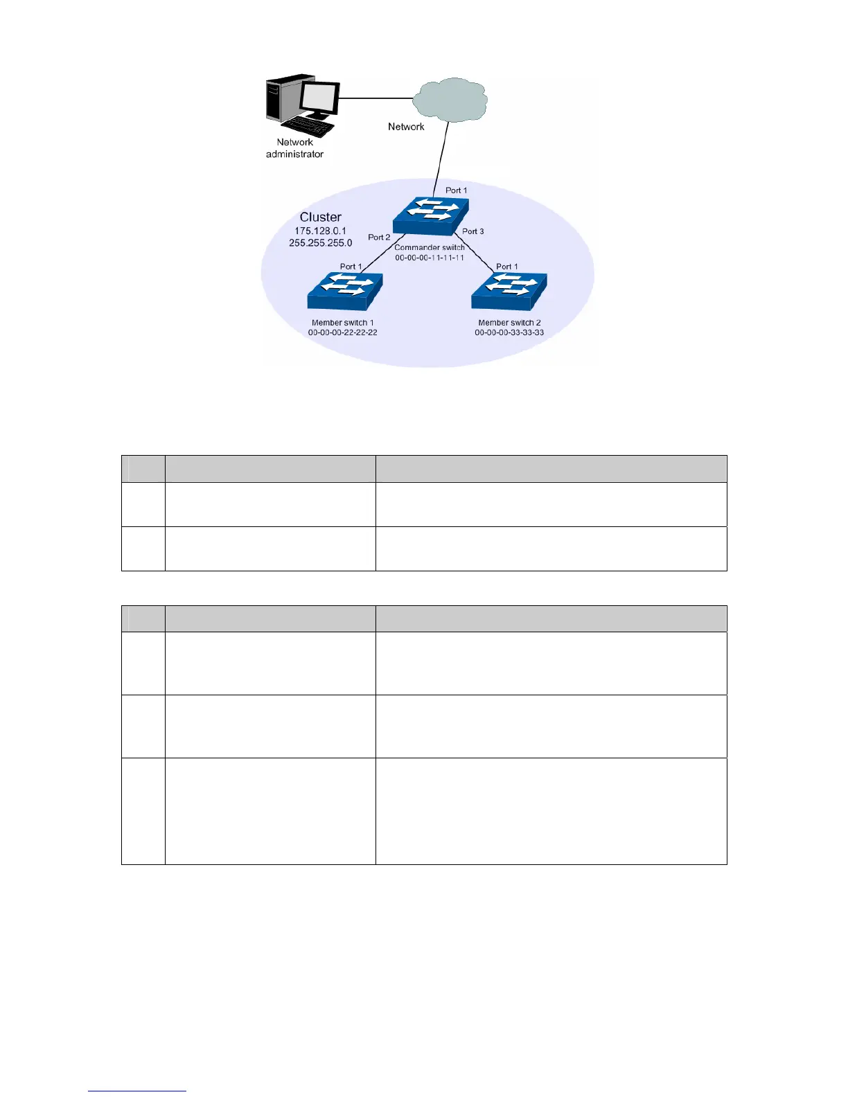
Figure 13-15 Network diagram
¾ Configuration Procedure
z Configure the member switch
Step Operation Description
1 Enable NDP function on the
switch and for port 1
On Cluster→NDP→NDP Config page, enable NDP
function.
2 Enable NTDP function on the
switch and for port 1
On Cluster→NTDP→NTDP Config page, enable
NTDP function.
z Configure the commander switch
Step Operation Description
1 Enable NDP function on the
switch and for port 1, port 2 and
port 3
On Cluster→NDP→NDP Config page, enable NDP
function.
2 Enable NTDP function on the
switch and for port 1, port 2 and
port 3
On Cluster→NTDP→NTDP Config page, enable
NTDP function.
3 Create a cluster and configure
the related parameters
On Cluster→Cluster→Cluster Config page, configure
the role as Commander and enter the related
information.
IP pool: 175.128.0.1
Mask: 255.255.255.0
197



 To Next Page