Do you have a question about the TR-Electronic CE-100 Series and is the answer not in the manual?
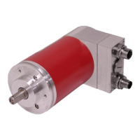
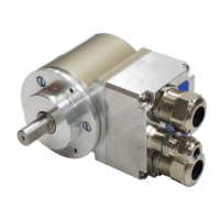
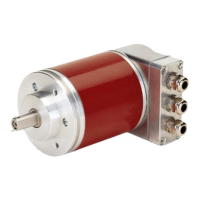
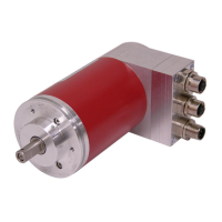
Describes the absolute rotary encoder series CE-65/CE-100 with PROFIBUS-DP interface.
Provides essential safety guidelines and precautions for operating the encoder.
Covers the process of installing the rotary encoder and its components.
Details the steps required for commissioning the rotary encoder.
Explains how to configure and parameterize the encoder settings.
Outlines methods for troubleshooting and using diagnostic options for the encoder.
Defines warning symbols, caution symbols, information symbols, and ESD precautions.
Discusses dangers from improper use, emphasizing technical faultlessness and adherence to the manual.
Details correct usage for angular motion measurement and industrial control, including forbidden applications.
Covers critical safety warnings like de-energizing the system, ESD protection, and proper disposal procedures.
Provides guidelines for safe transportation, including avoiding shocks, using original packaging, and storage conditions.
Details electrical ratings, output capacity, resolution, measuring range, interface specifications, and mechanical ratings.
Explains encoder shaft drive connection with elastic couplings, flange mounting, and clamping bracket mounting.
States the PNO ID number AAAB (hex) which is reserved and filed with the PNO.
Details how to set the station address using the rotary switch and the valid address range (3-99).
Covers PROFIBUS system connection, termination, cable parameters, transmission speeds, and shielded data cable requirements.
Explains the role of device master files (GSD) and type files for encoder configuration and integration.
Defines configuration as specifying process data length and type, and describes nominal configurations.
Explains parameterization for PROFIBUS-DP slaves, data entry via input masks, and dependency on nominal configuration.
Explains how to adjust the encoder position value using PROFIBUS.
Describes the teach-in function for linear axes, automatic calculation of measuring length.
Describes the separate Synchronous Serial Interface for position value availability to other units.
Explains the function of the red (BF) and green (STAT) LEDs for error and status indication.
Explains how PROFIBUS masters communicate faults to host systems and the role of diagnostic messages.
Lists common faults like vibrations, electrical faults, and shaft loading, with causes and remedies.
Summarizes new features in firmware version 4.x compared to 3.x, including commissioning function and scaling.
| Brand | TR-Electronic |
|---|---|
| Model | CE-100 Series |
| Category | Media Converter |
| Language | English |