Do you have a question about the TRACE ELLIOT 1210 and is the answer not in the manual?
Essential safety guidelines for electrical products, covering handling, installation, and maintenance procedures.
Information on permissible noise level exposures and the critical importance of using hearing protection.
Details the differences between 7 Band and 12 Band preamp sections and general design principles.
Explains the distinction between pre-set and performance functions and their switching mechanisms.
A direct comparison table highlighting key features available on 7 Band and 12 Band models.
Step-by-step instructions for the initial setup and basic operation of the amplifier.
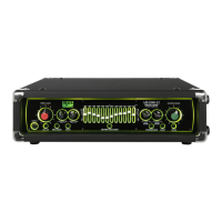
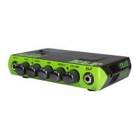
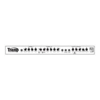
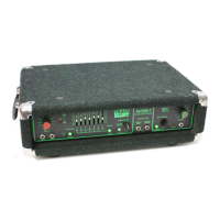
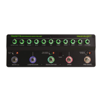
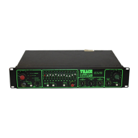
Illustrates and describes the physical layout of controls on the front panel for 7 Band and 12 Band models.
Details the input socket, sensitivity switch, gain control, and signal level indicators for optimal gain setting.
Explains the tuner output and the classic 'Mid Pre-Shape' circuit for tonal shaping.
Describes the valve circuit controls, including drive level and blending of normal and valve sounds.
Details the DI output socket, its pre/post switching, and the effects loop send/return connections.
Explains the function and usage of the graphic equalizer for precise tonal control.
Provides guidance on using graphic equalizer sliders for optimal bass guitar tone shaping.
Details the single-band compressor, its soft-knee design, and operation for dynamic range control.
Explains the compressor's adaptive attack/release and single control for ease of use.
Introduces the dual-band compressor and its controls for low-frequency dynamics.
Details the high-band compressor control for high-frequency dynamics and its specific design.
Explains the unity gain series effects loop for integrating external units.
Describes the effects loop switch, mute function for silent tuning, and output level adjustment.
Explains the function of the multi-purpose LED and the unbalanced line output for external equipment.
Details the connection for the footcontroller and its functions for both 7 and 12 Band models.
Explains the DI earth lift switch for hum reduction and the filtered SEND outputs for effects loops.
Describes the configuration options for effects loops (series/parallel) and the return connections.
Details the loop level control and provides suggested configurations for using the effects loop.
Explains the tuner output, balanced DI outputs, and stereo/mono signal routing.
Details the Speakon and 1/4" jack speaker outputs and recommended cabling practices.
Explains the control for front panel backlighting brightness and the main power switch operation.
Details the mains power connection via the IEC socket and the importance of correct fuse replacement.
Discusses the high-efficiency advanced design of the power amplifier sections and their protection features.
Explains the anti-clipping circuit and provides details on various combo configurations and their features.
Provides a guide to diagnosing and resolving common operational problems with the unit.
Offers example settings for different sound profiles, encouraging experimentation.
Illustrates the basic signal flow through the 7 Band amplifier circuitry.
Illustrates the basic signal flow through the 12 Band amplifier circuitry, including stereo aspects.
Provides detailed technical specifications for both 7 Band and 12 Band models.
Lists specifications for various combo enclosure models, including transducer complement and power handling.
Provides physical dimensions and weight for different amplifier and combo models.
Defines technical terms used throughout the manual for better understanding.
Continues the definitions of technical terms used in the manual.
| Brand | TRACE ELLIOT |
|---|---|
| Model | 1210 |
| Category | Amplifier |
| Language | English |