By using the two controls a wide range of valve sounds can be dialled in, from vintage warmth to heavy
overdrive. Bear in mind this is not simulation, this is a real valve doing a real job. We recommend experimenting
with both the PRE SHAPE and GRAPHIC EQ in various settings while the VALVE circuit is switched on.
With PRE SHAPE selected and a low to medium amount of DRIVE, the sound takes on the character of a
vintage valve bass amp due to ‘shaping’ the signal before the valve. With higher DRIVE settings the tone
often benets from some sound ‘sculpting’ by the GRAPHIC, a little boost in the high mids helps the attack.
Also the COMPRESSOR can be used to further shape the tone. The HIGH BAND is of particular use when
lots of overdrive is being produced due to the extra high frequency content in the sound.
Basically, this is a very versatile circuit that can produce various valve tones, from demurely subtle to wantonly
lthy! Experiment and enjoy.
Once a particular sound is found, the user can switch to the normal, clean sound and back again by pressing
the associated switch on the front panel or by using the footcontroller, both of which have a red LED to show
its status.
Please note: to drive the valve hardest the INPUT GAIN control needs to be set correctly as described above.
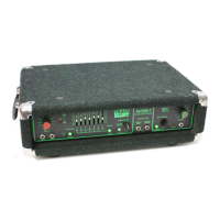
(10) DI OUT XLR socket (7 Band)
This is a low impedance balanced output for connecting direct to a stage box or mixer for live or studio use.
It gives the engineer a strong, clean signal without any overspill from other instruments. The XLR socket is
wired as normal: pin 1 = Ground, pin 2 = Signal +, pin 3 = Signal –
(An ‘Earth Lift’ switch is featured on the rear panel - see below).
(11) PRE/POST switch (7 Band)
This switches the signal that appears at the DI OUT from PRE with the switch out, to POST with the switch
in.
PRE is before any EQ is applied, therefore a higher level, buffered, version of the input signal. POST is after
the EQ, COMPRESSOR and effects loop, but before the OUTPUT LEVEL control. Therefore, any sound
shaping that is applied within the amplier will be heard on the DI signal as well. Different applications will
determine different settings. If in doubt choose POST as this will be basically the same sound that will be
heard from the cabinet / combo speakers.
Both settings should have similar general output levels. Neither will be affected by adjustments to the OUTPUT
LEVEL, so turning up on stage will not overload the mixing desk once it is set. In either setting the output will
be muted if the MUTE function is used.
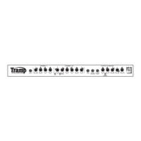
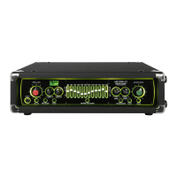
(12) GRAPHIC EQUALIZER switch & sliders
When switched on the GRAPHIC EQUALIZER will be inserted into the signal chain. The green LED above
the sliders shows its status. It can be switched on and off using the front panel switch and also from the
footcontroller.
The graphic equalizer is the centre piece, both functionally and quite literally, of a traditional Trace Elliot
amplier, so much so that the actual name for each part of the range is derived from the number of frequency
bands within each one, i.e. 7 Band and 12 Band. Both types are very powerful tools for controlling the tone
of your instrument. The design of a Trace Elliot graphic equalizer is very different from a standard sound
reinforcement EQ. 15dB of cut or boost is available for each band, but instead of being spread mathematically
over the frequency range they have been set at carefully selected frequencies of particular use for bass guitar.