OPERATION
Page
60
Copyright Trace Engineering Company, Inc.
5916 - 195th Street N. E.
Arlington, WA 98223
Telephone: 360/435-8826
Fax: 360/435-2229
www.traceengineering.com
SW Series Inverter/Charger
Part No. 2031-5
Rev. B: Sept 1, 1999
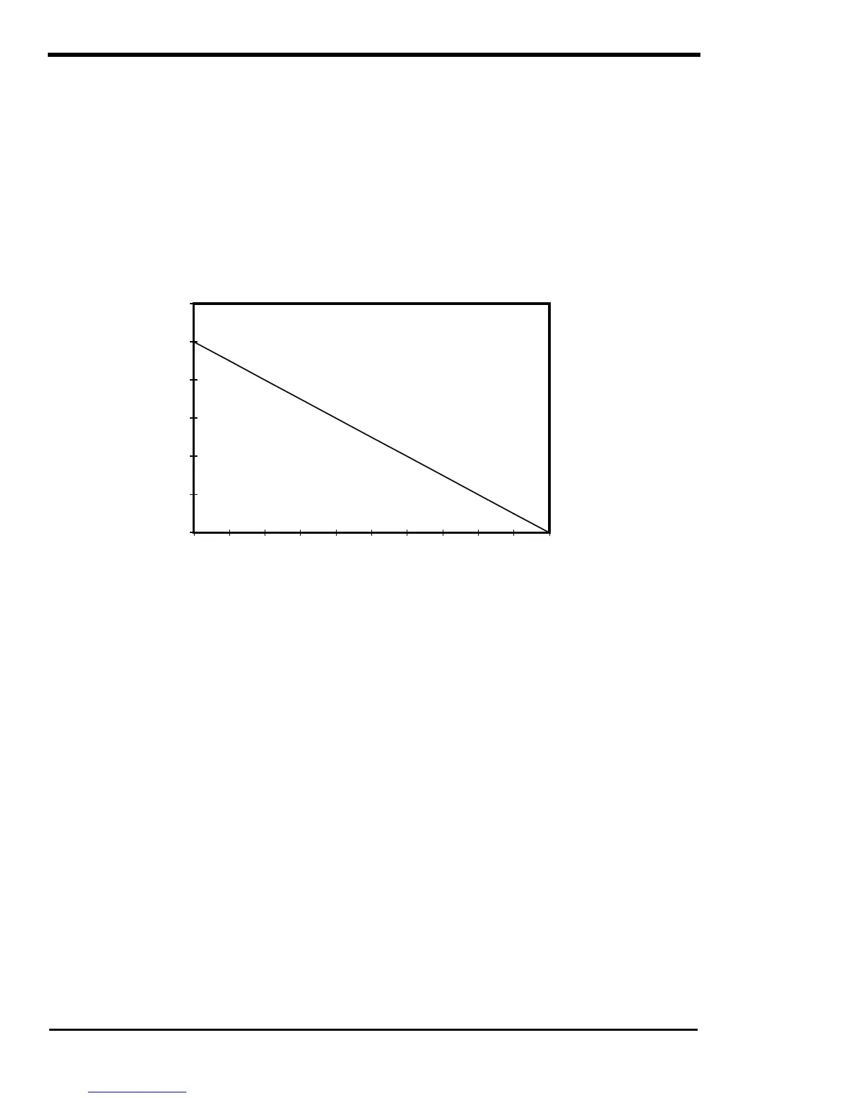
INVERTER CAPACITY VS TEMPERATURE
The current protection circuit in the SW Series Inverter/Charger is temperature compensated, therefore
the maximum sized load that the inverter can run changes with temperature. As the temperature of the
power devices (FET’s) increase, the allowable current is reduced. When the available current is reduced,
the capacity of the inverter to run loads is reduced.
The graph below shows the effect temperature has on the inverter’s capacity to run loads, notice that the
inverter reduces its capacity at temperature above 25 °C. The temperature derating graph assumes that
the inverter is at sea level and the airflow to the inverter is unrestricted.
Figure 20, Inverter Capacity vs. Temperature
Temperature Derating for SW Series Inverters
0
20
40
60
80
100
120
25 32.5 40 47.5 55 62.5 70 77.5 85 92.5 100
Percent
of
total
rated
power
capacity
Temperature °C
 Loading...


