EasyManua.ls Logo

TradePro TP-P-521 - User Manual

Default Icon
9 pages
Print Icon
To Next Page IconTo Next Page
Loading...
This thermostat requires 24 Volt AC Power or two (2) properly installed
“AA Alkaline batteries for proper operation. When connecting 24 Volt
AC Power the batteries may be installed as a backup.
Thermostat
installation and all components of the system shall conform to
Class II Circuits per NEC code.
For use only as described in this manual. Any other use will void warranty.
TP-P-511
Single Stage Heat / Cool
Conventional and Heat Pump
1
Specifications
2
Installation
3
Setting User Options
4
Setting Your Program Schedule
5
Operating Your Thermostat
6
Additional Operation Features
7
Thermostat Maintenance
Warning
Turn off power to the heating or cooling
equipment before installation.
Attention
For installation by experienced service
technicians only.
TP-P-521
Up to 2 Heat / 1 Cool
Conventional and Heat Pump
Read all instructions before proceeding.
This thermostat is compatible with:
• Single stage heat / cool conventional and heat pump systems
• Conventional systems up to 2 heat / 1 cool (TP-P-521)
Single compressor heat pump systems with an auxiliary heat stage (TP-P-521)
• 250 – 750 millivolt heat only systems
Electrical and control specifications:
• Electrical Rating: 24 Volt AC
• 1 amp maximum load per terminal
• AC Power: 18 – 30 Volts AC
• DC Power: 3.0 Volt DC (2 “AA Alkaline Batteries Included)
• Control Range: 45° – 90° F (7° – 32° C)
• Temperature Accuracy: +/- 1° F (+/- .5° C)
Terminations
• TP-P-511 – Rc, Rh, O, B, Y1, W1, G, C
• TP-P-521 – Rc, Rh, O, B, Y1, E/W1, G, W2, C
1
Specifications
TPP-100-01
Model number is located on
back of thermostat
Programmable Thermostats
User
Manual
®
Question and Answer IconNeed help?

Do you have a question about the TradePro TP-P-521 and is the answer not in the manual?

Summary

Specifications

Electrical and Control Specifications

Lists voltage, current, control range, and temperature accuracy.

Installation

Thermostat Location

Guidance on ideal placement for accurate temperature sensing.

Provide Power

Details powering the thermostat via AC or battery backup.

Connect Your Wires

Conventional Systems Wiring

Wiring configurations for various conventional HVAC systems.

Heat Only or Millivolt Wiring

Wiring for heat-only or millivolt conventional systems.

1 HEAT; 1 COOL Wiring

Wiring for conventional systems with one stage heat and cool.

2 HEAT; 1 COOL Wiring (TP-P-521)

Wiring for TP-P-521 conventional systems with two heat/one cool.

Set Installer Switches

Switch Configuration

Details on setting installer switches for system type and temperature scale.

Setting Your Program Schedule

Operating Your Thermostat

Thermostat Maintenance

Overview

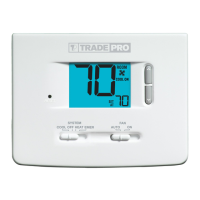
This document is a user manual for TRADEPRO® Programmable Thermostats, specifically models TP-P-511 and TP-P-521. It provides instructions for installation, operation, and maintenance of these devices.

The TP-P-511 is a single-stage heat/cool conventional and heat pump thermostat. The TP-P-521 is a two-heat/one-cool conventional and heat pump thermostat, also supporting single compressor heat pump systems with an auxiliary heat stage. Both models are compatible with 250-750 millivolt heat-only systems.

Technical Specifications:

  • Electrical Rating: 24 Volt AC
  • Maximum Load per Terminal: 1 amp
  • AC Power: 18 – 30 Volts AC
  • DC Power: 3.0 Volt DC (requires two "AA" Alkaline Batteries, included)
  • Control Range: 45° - 90° F (7° – 32° C)
  • Temperature Accuracy: +/- 1° F (+/- .5° C)

Terminations:

  • TP-P-511: Rc, Rh, O, B, Y1, W1, G, C
  • TP-P-521: Rc, Rh, O, B, Y1, E/W1, G, W2, C

Installation:

Installation requires turning off power to the heating or cooling equipment. The thermostat should be installed approximately 5 feet (1.5m) above the floor in an area with good air circulation and average room temperature, avoiding drafts, dead air spots, direct sunlight, and proximity to heat sources or outside walls.

The installation process involves five basic steps:

  1. Install the Sub-Base: Remove the sub-base from the thermostat body and mount it using the supplied anchors for drywall or plaster. Pilot holes of 3/16" are recommended.
  2. Provide Power: For 24 Volt AC power, connect the common side of the transformer to the C terminal on the sub-base. For primary or backup power, insert two "AA" alkaline batteries into the battery compartment, ensuring correct polarity.
  3. Connect Your Wires: The manual provides detailed wiring configurations for conventional systems (Heat Only or Millivolt, 1 Heat/1 Cool Single or Dual Transformer, 2 Heat/1 Cool Single or Dual Transformer for TP-P-521) and heat pump systems (1 Heat/1 Cool - No Auxiliary Heat, 2 Heat/1 Cool - Including Auxiliary Heat for TP-P-521). Notes specify conditions for optional common connections, jumper removal for dual transformer systems, and changeover valve selection.
  4. Set Installer Switches: Switches located on the back of the thermostat must be configured correctly for proper operation. These include:
    • CONV/HP: Selects between conventional and heat pump systems.
    • F/C: Selects between Fahrenheit and Celsius temperature scales.
    • HE/HG: Selects between gas heat (HG) and electric heat (HE). A reset button must be pressed after making any changes to these switches.
  5. Attach Thermostat to Sub-Base: Align the thermostat body with the sub-base and push until it snaps into place. Insert the quick reference card into the slot on top.

Usage Features:

  • Setting User Options (Advanced): Users can customize thermostat features. To access the menu, hold the RETURN button for approximately 3 seconds. Options include:
    • 1st Stage Differential: Selects a temperature differential of 0.5°, 1°, or 2°F (0.2°, 0.5°, or 1°C).
    • 2nd Stage Differential (TP-P-521): Selects a temperature differential of 1°, 2°, 3°, 4°, 5°, or 6°F (0.5°, 1°, 1.5°, 2°, 2.5°, or 3°C).
    • Extended Hold Period: Selects long (permanent) hold mode or 24-hour (temporary) hold mode.
    • Filter Service Monitor: Disables the feature or sets a reminder for 30, 60, 90, 120, 180, or 365 days.
    • Adaptive Recovery Mode (ARM™): Disables or enables adaptive (early) recovery mode.
  • Setting the Time and Day: Press DAY/TIME, then use the up/down arrows to adjust the hour, minute, and day of the week. Press RETURN to exit.
  • Setting Your Program Schedule (5-2 Day Residential): The thermostat comes with a default energy-saving program. To program a custom schedule:
    1. Press PROG. The display will show M, TU, W, TH, F, and the hour will flash.
    2. Move the SYSTEM switch to HEAT or COOL.
    3. Use up/down arrows to adjust the hour for the MORN event, then press PROG.
    4. Adjust the minute for MORN, then press PROG.
    5. Adjust the temperature for MORN, then press PROG.
    6. Repeat for DAY, EVE, and NIGHT events.
    7. Repeat steps 3-6 for the weekend (S, SU) program.
    8. If needed, repeat steps 2-7 for the opposite mode (HEAT or COOL).
    9. Press RETURN to exit.
  • System Control Mode: The SYSTEM switch allows selection of:
    • COOL: Cooling system operates.
    • OFF: Heating and cooling systems are off.
    • HEAT: Heating system operates.
    • EMER (TP-P-521 Only): Operates a backup heat source (Emergency Heat) for heat pump systems. "NO EMER SET" flashes if EMER is selected for a conventional system.
  • Fan Control Mode: The FAN switch allows selection of:
    • AUTO: Fan runs only when heating or cooling system is running.
    • ON: Fan runs continuously.
  • Temperature Adjustment:
    • Temporary Adjustment: Use up/down arrows to adjust the current set point.
    • Extended Adjustment: Press HOLD until "HOLD" appears, then use up/down arrows to adjust the set temperature.
  • Status Indicators:
    • HEAT ON: Heating system is running.
    • COOL ON: Cooling system is running.
    • SERVICE: User-selected service reminder is active.
    • AUX (TP-P-521 Only): Auxiliary stage of heating is running (multi-stage systems).
    • EMER (TP-P-521 Only): Emergency heating system is running (heat pump systems).
  • Program Event Indicators: MORN, DAY, EVE, NIGHT indicators show the active program event. A flashing indicator means the program has been temporarily bypassed. Not visible in HOLD Mode.
  • Compressor Protection: An automatic delay prevents short cycling of the compressor, protecting the system from damage.

Maintenance Features:

  • Resetting the Thermostat: A small button labeled "reset" on the front housing, accessible with a toothpick or paperclip, erases all user settings and programming.
  • Changing the Batteries: When the low battery indicator appears, remove the thermostat body, replace the two "AA" alkaline batteries, ensuring correct polarity, and reattach the body. Annual battery replacement is recommended.
  • Thermostat Cleaning: Wipe the outer body with a soft damp cloth. Do not spray liquid directly on the thermostat or use abrasive cleansers.

Warranty:

TRADEPRO® offers a 3-year limited warranty against defects in material or workmanship from the original purchase date by a professional service technician. The warranty does not cover batteries, damage from accident, alteration, neglect, misuse, improper installation, or failure to follow instructions. Warranty service requires returning the thermostat postage prepaid with proof of purchase and a description of the malfunction.

TradePro TP-P-521 Specifications

General IconGeneral
BrandTradePro
ModelTP-P-521
CategoryThermostat
LanguageEnglish

Related product manuals