30
18-GF84D1-1B-EN
Blower Removal Instructions
SSttyyllee 11 WWaallll MMoouunntt ((55TTTTMM55BB00BB3300MM2211SSAA &&
55TTTTMM55BB00BB3366MM3311SSAA))::
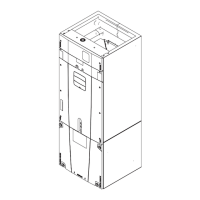
1. Turn off circuit breaker, unscrew and open upper
access panels for front return application and open
both upper and lower access panels for bottom
return applications.
2. Unplug wire harnesses connections from the
electrical box and motor.
3. Unscrew and pull the electrical box out of the unit
and set it aside.
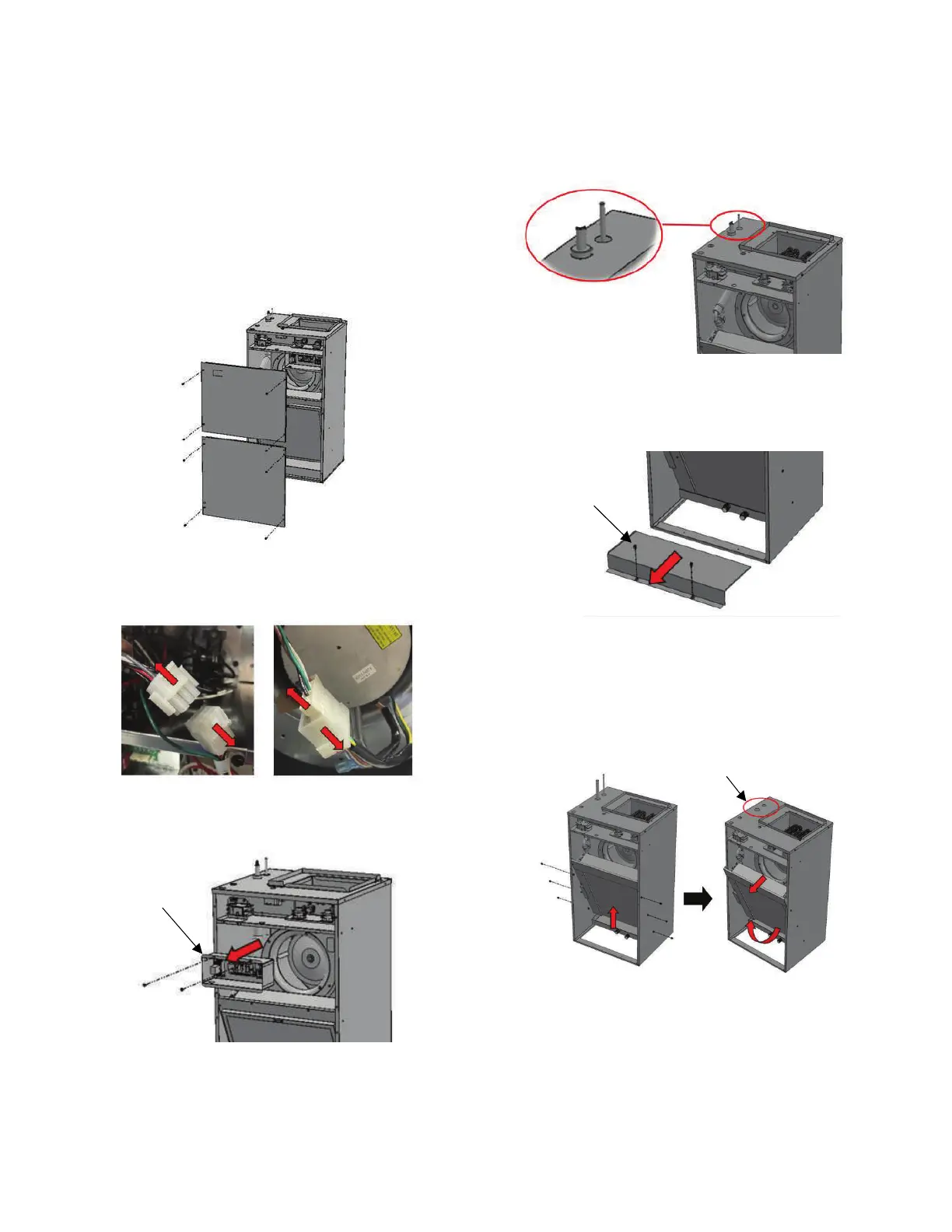
4. Cut the line set on the top plate.
NNoottee:: This step assumes that the refrigerant from the
system is fully recovered.
5. This step only applies to front return application
where drip shield is present. Remove 2 screws from
the drip shield and slide it out and set aside to
access the coil assembly.
6. Remove 3 screws on each side of the wrapper that
holds the coil assembly. (a) Pull up the coil slowly
from the drain pan and (b) tilt the coil out from the
bottom until the (c) suction and liquid line are inside
the unit, and finally, (d) pull the entire coil
assembly.
Suction & Liquid
Lines are in
7. Unscrew the blower assembly, (a) support and drop
the front end, then (b) slide it out of the plenum to
replace the motor or the blower assembly.
 Loading...