Adjusting the Tracer AdaptiView
Display Arm
The Tracer AdaptiView display arm may be too loose or
too tight and in need of adjustment. To adjust the tension
on the display arm:
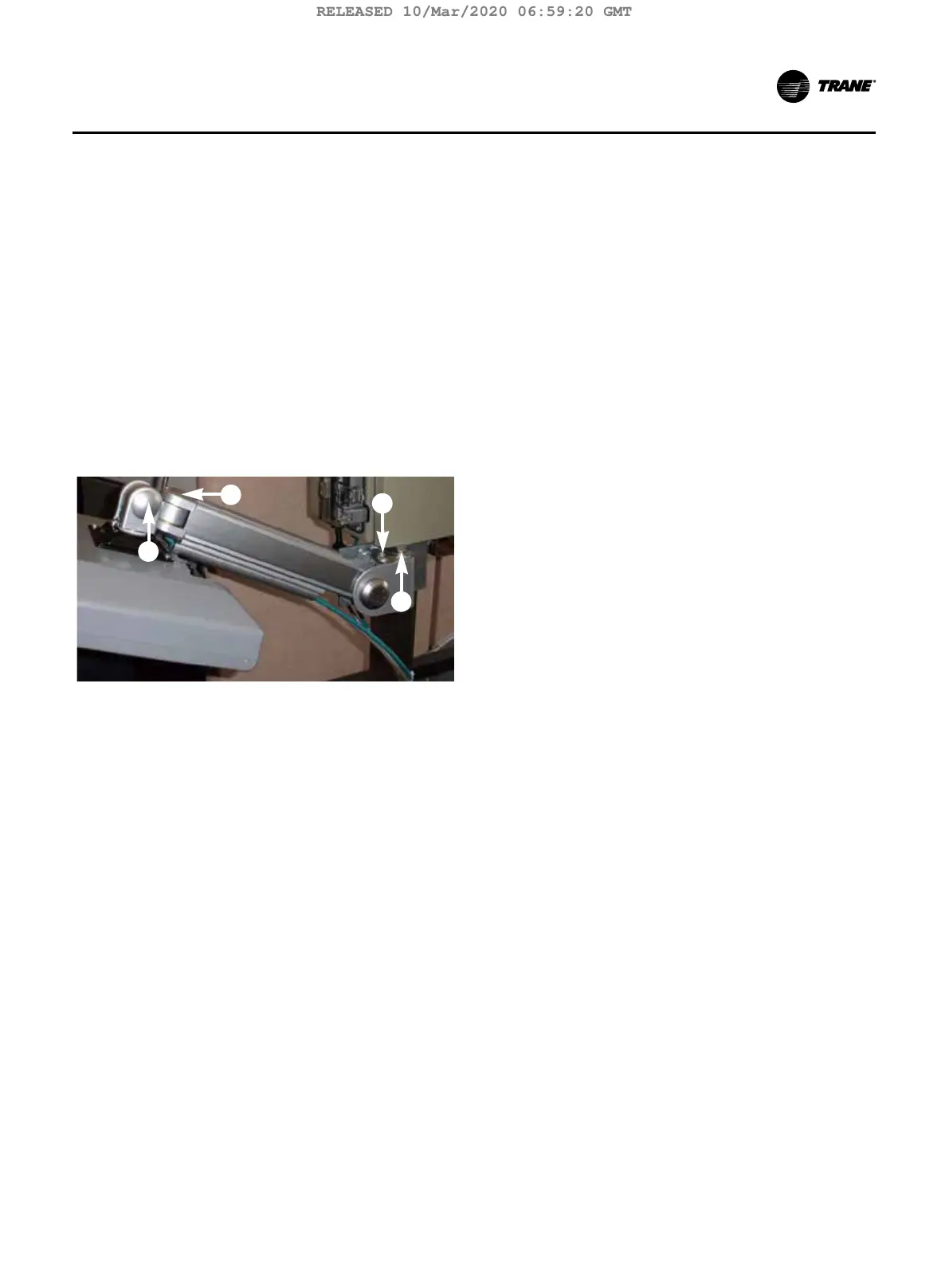
1. There are three joints on the display arm that allow
the Tracer AdaptiView display to be positioned at a
variety of heights and angles (refer to items labeled 1,
2, and 3 in Figure 20). At each joint in the display arm
there is either a hex bolt (1 and 2) or hex screw (3).
Turn the hex bolt or screw in the proper direction to
increase or decrease tension.
Note: Each hex bolt or screw is labeled with ‘loos-
en’/‘tighten’, or ‘+’/’–’ indicators.
Figure 20. Joint locations on the display arm
4
3
2
1
2. Joint 3 has a 6 mm hex screw controlling the tension
on a gas spring, which allows the Tracer AdaptiView
display to tilt up and down.
3. Joints 1 and 2 are covered by a plastic cap. Remove
the plastic cap to access the hex bolt. Adjust using a
13 mm wrench as necessary.
4. To adjust the swivel of the Tracer AdaptiView display
(the spin right and left similar to the steering wheel
on a car), you need to adjust the hex bolt located
inside the display arm back plate. This adjustment
needs to be done BEFORE attaching the display. Use
a 9/16” or 14 mm wrench.
5. Use a 13 mm wrench to adjust the bolt (item labeled
4 in Figure 20) that allows the entire display arm to
swivel to the left and right.
TCVHE-SVX04D-EN 37
Installation Controls
RELEASED 10/Mar/2020 06:59:20 GMT