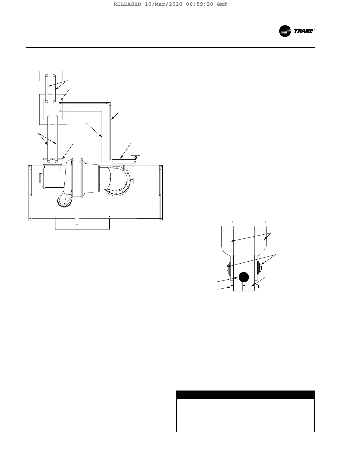
Figure 22. Typical equipment room layout for units with
remote-mounted starters
1
2
3
4
6
7
5
1. Line side power conduits
2. Remote-mounted starter
3. Unit control panel
4. IPC Circuit conduit less than 30V
Note: Must enter the low voltage Class 2 portion of the
unit control panel (1000 feet max).
5. Motor terminal box
6. 115 V Control conduit
Note: Must enter the higher than 30 Vdc Class 1 portion
of the until control panel.
7. Lead power wiring
Note: Refer to the unit field connection diagram for ap-
proximate unit control panel knock out locations.
Note: To prevent damage to the unit control panel com-
ponents, do not route control conduit into the top
of the box.
Starter to Motor Wiring (Re-
mote-Mounted Starters Only)
Ground Wire Terminal Lugs
Ground wire lugs are provided in the motor terminal box
and in the starter panel.
Terminal Clamps
Terminal clamps are supplied with the motor terminals
to accommodate either bus bars or standard motor
terminal wire lugs. Terminal clamps provide additional
surface area to minimize the possibility of improper elec-
trical connections.
Wire Terminal Lugs
Wire terminal lugs must be field supplied.
• Use field provided crimp type wire terminal lugs
properly sized for the application.
Note: Wire size ranges for the starter line and load-side
lugs are listed on the starter submittal drawings
supplied by the starter manufacturer or Trane.
Carefully review the submitted wire lug sizes for
compatibility with the conductor sizes specified
by the electrical engineer or contractor.
• A terminal clamp with a 3/8” bolt is provided on
each motor terminal stud; use the factory supplied
Belleville washers on the wire lug connections. The
figure below illustrates the juncture between a motor
terminal stud and terminal lug.
Figure 23. Terminal stud, clamp and lug assembly
2
1
3
4
5
1. Belleville washer
2. Terminal lugs
3. Terminal clamp
4. Motor terminal stud
5. 3/8” bolt
1. Torque for this assembly is 24 ft·lb (32.5 N·m).
2. Install but do not connect the power leads between
the starter and compressor motor. (These connec-
tions will be completed under supervision of a quali-
fied Trane service engineer after the pre-start inspec-
tion.)
D
NOTICE
Component Damage!
Ensure the power supply wiring and output to motor
wiring are connected to the proper terminals. Failure
to do so will cause catastrophic failure of the starter
and, or motor.
TCVHE-SVX04D-EN 45
Power Supply Wiring
RELEASED 10/Mar/2020 06:59:20 GMT