iiiiii!; iiiii!ii! Iii;;ii¸iI
iiii[iii
ConvertibleVariable Speed-
Communicating Air Handlers 2 112- 5 Ton
2/4TEE3C31A1000A, 2/4TEE3C37A1000A,
2/4TEE3C40A1000A, 2/4TEE3C49A1000A,
2/4TE E3C65A1000A
ALL phases of this installation must comply with NATIONAL, STATE AND LOCAL CODES
18-GELID1-4
IMPORTANT -- This Document is customer property and is to remain with this unit. Please return to service information
pack upon completion of work.
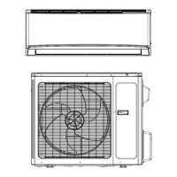
This Air Handler can be configured for Communicating
or 24VAC modes. Using fully Communicating or 24VAC
modes, the Air Handler can support multi or single
stage Heat Pump, cooling only, or cooling with electric
heat applications. Combined with a communicating
Comfort Control only, the Air Handler will support a
single stage 24VAC cooling outdoor unit.
THIS INFORMATION IS FOR USE BY INDIVIDUALS
HAVING ADEQUATE BACKGROUNDS OF ELECTRICAL
AND MECHANICAL EXPERIENCE. ANY ATTEMPT TO
REPAIR A CENTRAL AIR CONDITIONING PRODUCT
MAY RESULT IN PERSONAL INJURY AND/OR PROP-
ERTY DAMAGE. THE MANUFACTURER OR SELLER
CANNOT BE RESPONSIBLE FOR THE INTERPRETA-
TION OF THIS INFORMATION, NOR CAN IT ASSUME
ANY LIABILITY IN CONNECTION WITH ITS USE.
TO PREVENT SHORTENING ITS SERVICE LIFE, THE
AIR HANDLER SHOULD NOT BE USED DURING THE
FINISHING PHASES OF CONSTRUCTION OR REMOD-
ELING. The low return air temperatures can lead to the
formation of condensate. Condensate in the presence
of chlorides and fluorides from paint, varnish, stains,
adhesives, cleaning compounds, and cement creates a
corrosive condition which may cause rapid deteriora-
tion of the cabinet and internal components.
CONTENTS
General Information ...........................................
Installation Limitations& Recommendations........................
Two Piece Cabinet Disassembly
Unit Installation ...................................................
Vertical Upflow......................................................................
Vertical Uownflow .................................................................
Horizontal Left .......................................................................
Horizontal Right
Duct Connections
Refrigerant Piping ..............................................
Brazing to Evaporator Section .......................... _9
Condensate Drain Piping ...................................
Electrical-Power Wiring ...................................
Airflow Adjustment .............................................. ,_
Unit Test Mode ......................................................
User Interface Menus ..........................................
Air Handler Flash Codes .............................. iii>i
Field Wiring ...........................................................
Outline Drawings .................................................
Checkout Procedures .........................................
A. GENERAL INFORMATION
These instructions do not cover all variations in sys-
tems or provide for every possible contingency. Should
further information be desired or particular issues arise
which are not covered sufficiently by this manual, con-
tact your local distributor or the manufacturer as listed
on the Air Handler nameplate.
These Air Handlers are shipped from the factory in the
upflow or horizontal right configuration and are fully
convertible to downflow or horizontal left. Refer to Sec-
tion C beginning on page 4 for additional information.
INSPECTION
Check carefully for any shipping damage. This must be
reported to and claims made against the transportation
company immediately. Cheek to be sure all major com-
ponents are in the unit. Any missing parts should be re-
ported to your supplier at once, and replaced with au-
thorized parts only.
© 2008 Trane