EasyManua.ls Logo

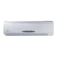
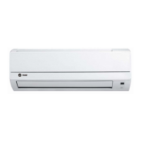
Trane 4MXW2336A1 User Manual

Trane 4MXW2336A1
48 pages
To Next Page IconTo Next Page
Page #1 background imageLoading...
Page #1 background image
Installer’s Manual
Split System (R-410A)
23 Series Single Zone
Inverter System
9,000 Btu/h to 36,000 Btu/h
Models:
HP Outdoor Units: HP Indoor Units:
4TXK2309A1 4MXW2309A1
4TXK2312A1 4MXW2312A1
4TXK2318A1 4MXW2318A1
4TXK2324A1 4MXW2324A1
4TXK2330A1 4MXW2330A1
4TXK2336A1 4MXW2336A1
June 2020 MS-SVN061C-EN

Questions and Answers:

Trane 4MXW2336A1 Specifications

General IconGeneral
BrandTrane
Model4MXW2336A1
CategoryAir Conditioner
LanguageEnglish

Summary

Safety Warnings and Symbol Definitions

Understanding Hazard Symbols

Explains WARNING, CAUTION, and NOTICE symbols for hazard identification.

General Safety Warnings for Installation

Key safety warnings related to installation, electrical work, and handling.

Refrigerant and Environmental Safety Precautions

R410-A Refrigerant and Equipment Safety

Safety warnings regarding R410-A refrigerant pressure and service equipment.

Detailed Safety Precautions for Installation

Electrical and Wiring Safety

Precautions for electrical connections, wiring, grounding, and power supply.

Refrigerant Handling and System Integrity

Safety measures for handling refrigerant, preventing contamination, and system pressure.

Unit Installation and Support Safety

Ensuring structural support and proper mounting to prevent accidents.

Advanced Safety and Pre-Installation Checks

System Operation and Grounding Safety

Safety tips for system pump-down, grounding, and power supply cable.

Installation Clearance Requirements

Piping Specifications and Operating Conditions

Refrigerant Piping and Brazing Safety

Hazardous Refrigerant Handling Warnings

Critical warnings about explosion, toxic gases, and proper refrigerant removal.

Nitrogen Purging for Brazing

Procedure for using nitrogen during brazing to prevent unit damage.

Selecting Proper Installation Locations

Indoor Unit Mounting Location and Preparation

Mounting Frame Installation

Steps for securely mounting the indoor unit's frame to the wall.

Drilling the Piping Hole for Unit Installation

Indoor Unit Refrigerant Piping Connection

Connecting Refrigerant Pipes Securely

Steps for connecting pipes to the indoor unit and tightening flare nuts.

Evacuation and Leak Testing Procedure

Vacuuming the system to 350 microns and leak checking connections.

Completing Indoor Piping and Insulation

Flare Connection Torque Specifications

Table detailing correct torque values for flare nut connections.

Condensate Drainage and Indoor Unit Wiring

Indoor Unit Electrical Wiring Steps

Procedure for opening the unit and threading the power connection wire.

Indoor Unit Wiring Connections and Grounding

Power and Signal Wire Connections

Connecting power and communication wires to terminals according to color coding.

Proper Grounding for Safety

Ensuring correct grounding of the unit to prevent electrical hazards.

Outdoor Unit Installation and Condensate Management

Refrigerant Piping Installation Techniques

Copper Tube Flaring Process

Proper procedure for flaring copper tubing for refrigerant connections.

Outdoor Piping and Insulation Procedures

Piping System Requirements and Oil Traps

Vacuuming and Leak Detection Procedures

System Vacuuming to Micron Levels

Ensuring the refrigeration circuit is evacuated to 350 microns.

Refrigerant Leak Checking Methods

Techniques for detecting refrigerant leaks using soap bubbles and pressure.

Electrical Wiring Precautions and Outdoor Connections

General Wiring Safety Warnings

Critical safety warnings for electrical wiring installation and grounding.

Electrical Requirements and Sizing

Power Supply and Circuit Requirements

Details on voltage, phase, and circuit requirements for the unit.

Electrical Installation Details

Post-Installation Checks and Test Operation

Pre-Test Installation Checklist

Points to check before performing the initial unit test.

Performing Unit Test Operation

Steps for turning on the unit and testing its modes.

Wiring Diagrams: Color Key and Indoor Units

Indoor Unit Wiring Diagrams

Indoor Unit Wiring Diagrams (Continued)

Outdoor Unit Wiring Diagrams

Outdoor Unit 9K-12K Wiring Diagram

Wiring diagram for outdoor units 9K and 12K.

Outdoor Unit Wiring Diagrams (Continued)

Outdoor Unit Wiring Diagram (Final)

Troubleshooting: Common Error Codes

Error Code Descriptions and Recommendations

Lists common error codes, malfunction types, and recommended actions.

General Troubleshooting Guide

Common Unit Operation Issues and Causes

Troubleshooting common problems like unit not running or unusual sounds.

General Maintenance and After-Sales Service

Related product manuals