18 18-AC104D1-1G-EN
24 VAC at plug J6
Standby B to R
1st Stage ON ON
B to R & Y1
2nd Stage ON OFF ON ON ON
B to R, Y1 & Y2
Standby OFF OFF
B to R & O
1st Stage ON
B to R, Y1 & O
2nd Stage ON OFF ON
B to R, Y1, Y2 & O
EEV control STATUS LED
1 sec 2 sec 3 sec 4 sec
ON Continuous
ON
OFFOFF
Heat
TABLE 3
Control Input and Status LED - J6
ON
Cool
OFF
OFF
OFF
OFF
ELECTRONIC EXPANSION VALVE (EEV) CONTROL BOARD
LED
Color
EEV
Fault LED
Description
3 Flash
Suction Pressure Transducer input is out of range
(Replace transducer) (1)
4 Flash
Suction Temperature Sensor input is out of range
(Replace sensor) (1)
5 Flash
Coil has short circuit
(Replace Coil) (2)
6 Flash
Valve is not responding to a position change command
(Possible stuck valve)
7 Flash
Valve is responding but system is not performing properly
(Low charge or restriction)
8 Flash
Compressor is not pumping
(3)
9 Flash
Low superheat in Cooling Mode
(Indoor TXV stuck open or ID Fan failure)
10 Flash
Not used at this time
(3) Monitor superheat and pressure: <3' SH for 5 minutes with valve @ minimum position, Monitor off-cycle
pressure and compare to next on-cycle for pressure drop within 60 seconds
Red
(1) Valve will close and LPCO will trip
OFF
1 Flash
Standby
Coil has an open circuit or intermittent short
(Replace Coil)
(2) Power supply will shut down to protect board
EEV Fault Codes
EEV not used on all models
2 Flash
Control has detected an internal failure
(Replace EEV control board)
The following may require additional diagnostics
Notes:
Printed from D802247P01 Rev08
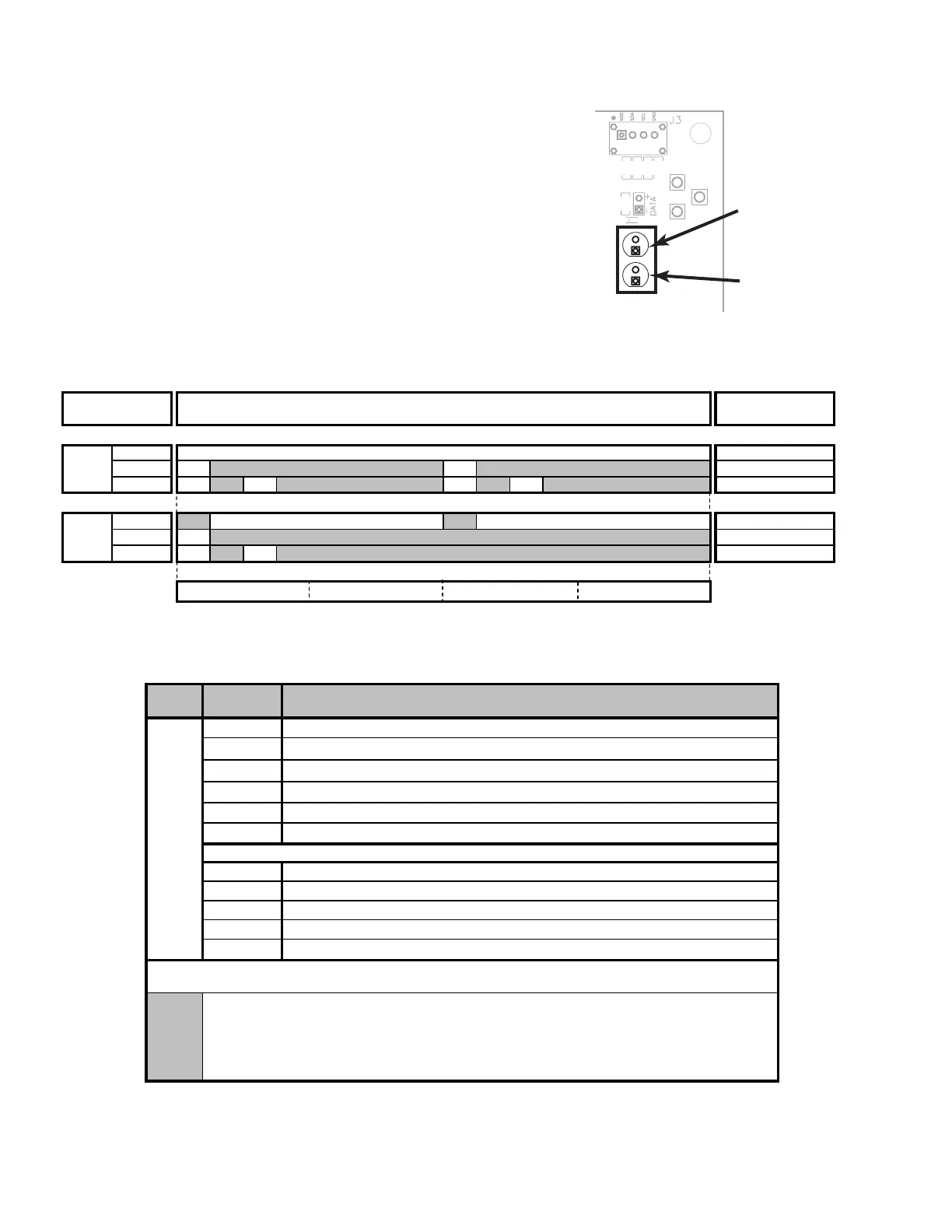
Fault LED (Red)
OPEN
CLOSE
TEST
STATUS LED
(Green)
Fault LED
(Red)
Status LED (Green)
On - Control has power
Flashing Fast - Control is driving valve (5 seconds max drive
time)
Flashing Pattern - See Table 6.
Fault Storing/CleAHRIng:
Faults 6-9 will be stored in non-volatile memory. See Close Valve Test for fault clearing procedure.
Faults 1-5 will clear with a power cycle.

 Loading...