EasyManua.ls Logo

Trane 4TWR6 Series User Manual

Trane 4TWR6 Series
28 pages
To Next Page IconTo Next Page
Page #1 background imageLoading...
Page #1 background image
18-AC104D1-1G-EN
ALL phases of this installation must comply with NATIONAL, STATE AND LOCAL CODES
IMPORTANTThis Document is customer property and is to remain with this unit. Please return to service informa-
tion pack upon completion of work.
These instructions do not cover all variations in systems or provide for every possible contingency to be met in connection with
the installation. Should further information be desired or should particular problems arise which are not covered sufficiently for the
purchaser’s purposes, the matter should be referred to your installing dealer or local distributor.
Note: The manufacturer recommends installing only approved matched indoor and outdoor systems. All of the manufacture’s split
systems are A.H.R.I. rated only with TXV/EEV indoor systems. Some of the benefits of installing approved matched indoor and
outdoor split systems are maximum efficiency, optimum performance and the best overall system reliability.
Table of Contents
Section 1. Safety ..................................................................................... 2
Section 2. Unit Location Considerations ............................................. 3
Section 3. Unit Preparation .................................................................... 4
Section 4. Setting the Unit ..................................................................... 4
Section 5. Refrigerant Line Considerations ......................................... 4
Section 6. Refrigerant Line Routing ..................................................... 5
Section 7. Refrigerant Line Brazing ...................................................... 7
Section 8. Refrigerant Line Leak Check ............................................... 7
Section 9. Evacuation ............................................................................ 8
Section 10. Service Valves .................................................................... 8
Section 11. Electrical - Low Voltage ..................................................... 9
Section 12. Electrical - High Voltage .................................................. 10
Section 13. Start Up .............................................................................. 10
Section 14. System Charge Adjustment ............................................. 10
Section 15. Checkout Procedures ...................................................... 14
Section 16. Defrost Control ................................................................. 15
Section 17. Troubleshooting ............................................................... 20
Section 18. Wiring Diagrams ............................................................... 22
Section 19. Pressure Curves ............................................................... 25
Section 20. Refrigerant Circuit (only for reference) .......................... 28
Heat Pumps
4TWR6
Installation and Operation Manual
Question and Answer IconNeed help?

Do you have a question about the Trane 4TWR6 Series and is the answer not in the manual?

Trane 4TWR6 Series Specifications

General IconGeneral
Series4TWR6
TypeHeat Pump
RefrigerantR-410A
Voltage208/230V
Warranty10 Year Limited Warranty on compressor, 10 Year Limited Warranty on outdoor coil

Summary

Section 1. Safety

Section 2. Unit Location Considerations

Unit Dimensions and Weight

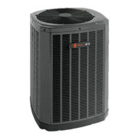
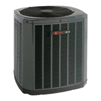
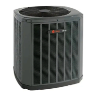
Provides specifications for unit dimensions and weight for various models.

Refrigerant Piping Limits

Details maximum lengths and vertical changes for refrigerant lines.

Suggested Locations for Best Reliability

Offers guidance on optimal placement for unit performance and longevity.

Section 3. Unit Preparation

Prepare The Unit For Installation

Step-by-step instructions for preparing the unit before installation.

Section 4. Setting the Unit

Pad Installation

Key considerations for installing the unit on a support pad.

Section 5. Refrigerant Line Considerations

Refrigerant Line and Service Valve Connection Sizes

Specifies line and service valve connection sizes for different models.

Factory Charge

Details the factory refrigerant charge and verification methods.

Section 6. Refrigerant Line Routing

Precautions

Guidelines to prevent noise transmission and ensure proper line routing.

Section 7. Refrigerant Line Brazing

Braze The Refrigerant Lines

Step-by-step procedure for brazing refrigerant lines to service valves.

Section 8. Refrigerant Line Leak Check

Check For Leaks

Procedure for pressurizing lines and checking for leaks using nitrogen.

Section 9. Evacuation

Evacuate the Refrigerant Lines and Indoor Coil

Instructions for evacuating the system to a specific micron level.

Section 10. Service Valves

Open the Gas Service Valve

Procedure for opening the gas service valve after evacuation.

Open the Liquid Service Valve

Procedure and safety precautions for opening the liquid service valve.

Section 11. Electrical - Low Voltage

Low Voltage Hook-up Diagrams

Illustrates low voltage wiring connections for different thermostat types.

Defrost Control

Explains defrost control settings, termination temperatures, and pin identification.

Section 12. Electrical - High Voltage

High Voltage Power Supply

Addresses high voltage power supply requirements and safety.

High Voltage Disconnect Switch

Details the installation of a separate disconnect switch for high voltage.

Section 13. Start Up

System Start Up

Step-by-step guide for safely starting up the installed system.

Section 14. System Charge Adjustment

Temperature Measurements

Describes necessary temperature measurements for system charging.

Subcooling Charging in Cooling (Above 55° F Outdoor Temp.)

Procedure for subcooling charging in cooling mode above 55°F.

Subcooling Charging Below 55° F Outdoor Temp. (In Heating Only)

Procedure for charging in heating mode below 55°F.

Section 15. Checkout Procedures

Operational And Checkout Procedures

Checklist for verifying system operation and installation after completion.

Section 16. Defrost Control

Defrost Termination Temperatures

Details selectable defrost termination temperatures based on ambient conditions.

Section 17. Troubleshooting

Section 18. Wiring Diagrams

Section 19. Pressure Curves

Section 20. Refrigerant Circuit (only for reference)

Related product manuals