18-BB34D1-19B-EN
21
NNoottee:: It may be necessary to replace permanent filters
annually if washing fails to clean the filter or if
the filter shows signs of deterioration. Be sure to
use the same type and size as was originally
installed.
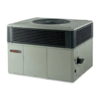
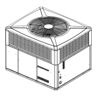
CCoonnddeennsseerr CCooiill
Be sure to keep all vegetation and debris away from the
condenser coil area.
Service Maintenance
CCoooolliinngg SSeeaassoonn
To keep the unit operating safely and efficiently, the
manufacturer recommends that a qualified service
technician check the entire system at least once each
year or sooner if needed. The service technician should
examine these areas of the unit:
• filters (for cleaning or replacement)
• motors and drive system components
• economizer gaskets (for possible replacement)
• safety controls (for mechanical cleaning)
• electrical components and wiring (for possible
replacement and connection tightness)
• condensate drain (for proper sealing and cleaning)
• unit duct connections (to see that they are
physically sound and sealed to the unit casing)
• unit mounting support (for structural integrity)
• the unit (for obvious unit deterioration)
HHeeaattiinngg SSeeaassoonn
Complete the following unit inspections and service
routines at the beginning of each heating season.
• Visually inspect the unit to ensure that the airflow
required for combustion and condenser coil is not
obstructed from the unit.
• Inspect the control panel wiring to verify that all
electrical connections are tight and that the wire
insulation is intact.
IInnddoooorr FFaann MMoottoorr SSppeeeedd TTaapp SSeettttiinngg
The units are factory set to medium speed.
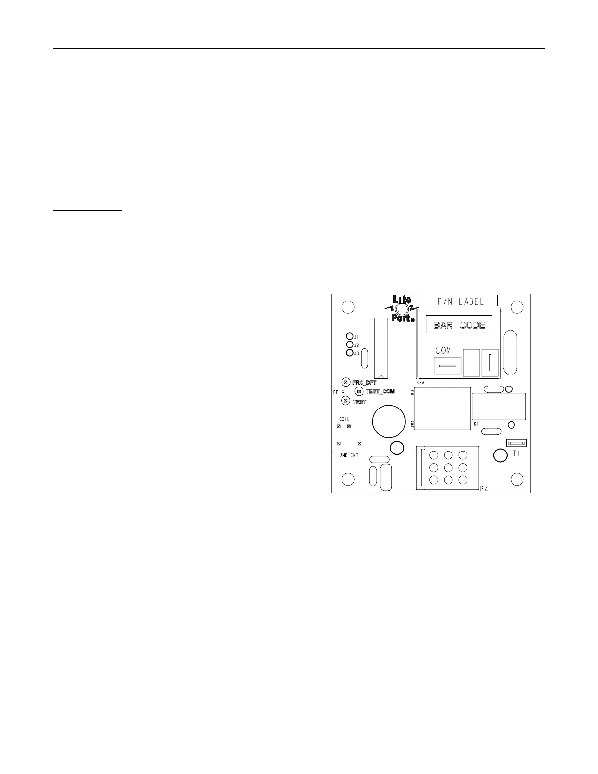
Fault Detection
A fault condition is indicated by the flashing light on
the defrost control board located inside the heat pump
control box.
In normal operation, the defrost control light will flash
once each second. If the light is flashing more than
once per second or not at all, refer to the Demand
Defrost Control Checkout table.
PPIINN IIddeennttiiffiiccaattiioonn
1. TEST_COMMON (Shorting any of the other pins to
this pin causes the function of the other pin to be
executed. Leaving this pin open results in the
normal mode of operation.)
2. TST = Test (Shorting TEST_COMMON to this pin
speeds up all defrost board timings.)
3. FRC_DFT = Forced Defrost (Short TEST_COMMON
to this pin for two (2) seconds to initiate a forced
defrost. Remove the short after defrost initiates.)
DDeeffrroosstt CCoonnttrrooll CChheecckkoouutt
Normal operation requires:
• LED on board flashing 1 time/second.
• 24V AC between R & B
• 24V AC between Y & B with unit operating
• Defrost initiation when FRC_DFT pin is shorted to
TEST_COMMON pin.
If a defrost control problem is suspected, proceed to
the Demand Defrost Control Checkout table.
TTeesstt SSeennssoorrss
Using the chart below, locate (as close as possible) the
actual sensor temperature. The measured resistance
should be relatively close to the resistance value
shown in the chart.
Example:
Sensor temp. = 19°F.
Measured Resistance = 46K ohms
This sensor is good since the measured value is
relatively close to the chart value.
UUnniitt SSttaarrttuupp