Page 4
Installer’s Guide
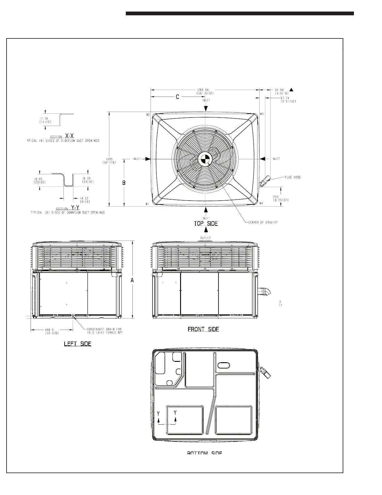
Step 2—Determine Unit Clearances
Figure 1. 4YCZ6024, 6036 (1 of 3)
Figures 1 through 6 show the unit critical dimensions.
NOTE: The view labeled “Bottom
Side” represents the Base
as viewed looking up from
underneath the unit.
 Loading...