EasyManua.ls Logo

Trane 4YCZ6024A1060A User Manual

Trane 4YCZ6024A1060A
40 pages
To Next Page IconTo Next Page
Page #1 background imageLoading...
Page #1 background image
SSAAFFEETTYY WWAARRNNIINNGG
Only qualified personnel should install and service the equipment. The installation, starting up, and servicing of heating, ventilating, and air-conditioning
equipment can be hazardous and requires specific knowledge and training. Improperly installed, adjusted or altered equipment by an unqualified person
could result in death or serious injury. When working on the equipment, observe all precautions in the literature and on the tags, stickers, and labels that
are attached to the equipment.
December 2022 1188--EEBB2288DD11--1122CC--EENN
Single Packaged Gas/Electric 16 SEER Convertible,
2 - 5 Ton, 60 - 115 KBTU, R-410A
4YCZ6024A1060A
4YCZ6036C1070B
4YCZ6036C1090B
4YCZ6036A3075C
4YCZ6036A3096C
4YCZ6036A4075D
4YCZ6036A4096D
4YCZ6048C1090A
4YCZ6048C1115A
4YCZ6048A3096C
4YCZ6048A3120C
4YCZ6048A4096D
4YCZ6048A4120D
4YCZ6060C1115A
4YCZ6060A3120C
4YCZ6060A4120D
NNoottee:: “Graphics in this document are for representation
only. Actual model may differ in appearance.”
NNoottee:: “Unit specific Service Facts available online.”
Installation and Operations Manual
Question and Answer IconNeed help?

Do you have a question about the Trane 4YCZ6024A1060A and is the answer not in the manual?

Trane 4YCZ6024A1060A Specifications

General IconGeneral
Model Number4YCZ6024A1060A
CategoryChiller
TypeAir Cooled
RefrigerantR-410A
Compressor TypeScroll
Cooling Capacity24, 000 BTU/hr

Summary

Introduction, Unit Inspection and Specification

Introduction

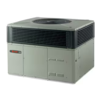
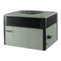
Basic overview of the manual's content and purpose.

Inspect Shipment

Procedures for checking the unit for damage upon delivery.

Product Specifications

Charging Procedures

Charging in Cooling above 55°F OD Ambient

Guidelines for system charging at moderate outdoor temperatures.

Charging Below 55°F

Instructions for system charging in colder outdoor conditions.

Unit Clearances

Determine Unit Clearances

Specifies required space around the unit for installation and service.

Dimensions and Clearances

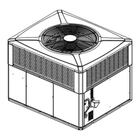
Provides physical unit dimensions and clearance requirements.

Location and Recommendation Information

Horizontal Airflow Unit Placement

Recommendations for siting units with horizontal airflow.

Down Airflow Unit Placement

Recommendations for siting units with downflow airflow.

Unit Installation

Flue Hood and Ground Level Installation

Covers flue hood attachment and ground-level unit placement.

Rooftop Installation Methods

Guidelines for installing units on rooftops using curbs or frames.

Airflow Conversion

Procedure to convert the unit's airflow from horizontal to downflow.

Lifting and Rigging

Rooftop Installation – Frame Mounting

Rooftop Installation – No Curb/ Frame

Ductwork Installation

Attaching Downflow Ductwork

Procedures for connecting downflow ductwork to the unit.

Attaching Horizontal Ductwork

Condensate Drain Piping

Gas Piping Installation

Gas Pressure Set-up Precautions

Safety and setup guidelines for gas piping connections.

Gas Supply Line Pressure

Procedures for checking and setting gas supply line pressure.

Air Filter Installation

Electrical Wiring

Electrical Connections

Details on making electrical connections according to codes.

Electrical Power

Requirements for ensuring proper electrical power supply to the unit.

Disconnect Switch

Power Wiring

Control Wiring

Thermostat Heat Anticipator

Unit Startup

Pre-Start Quick Checklist

A checklist of items to verify before starting the unit.

Cooling Operation

Procedures for starting the unit in cooling mode and checking pressures.

Gas Heating Mode Startup

Sequence of Operation

Final Installation Checklist

Maintenance

Owner Maintenance Procedures

Tasks the owner can perform for routine unit care.

Service Maintenance

Recommended maintenance tasks for qualified service personnel.

Manifold Pressure Adjustment

Procedure for checking and adjusting gas manifold pressure.

ECM Fan Motor Adjustments

Pressure Curves

Cooling Pressure Curves

Graphs showing expected operating pressures for cooling mode.

Indoor Fan Performance

Refrigerant Circuit

Cooling Refrigeration Cycle Diagram

A diagram illustrating the cooling refrigeration cycle components.

Troubleshooting Chart

Important Product Information

Service Information

Basic troubleshooting steps for the owner before calling for service.

Related product manuals