18-BC118D1-1A-EN 11
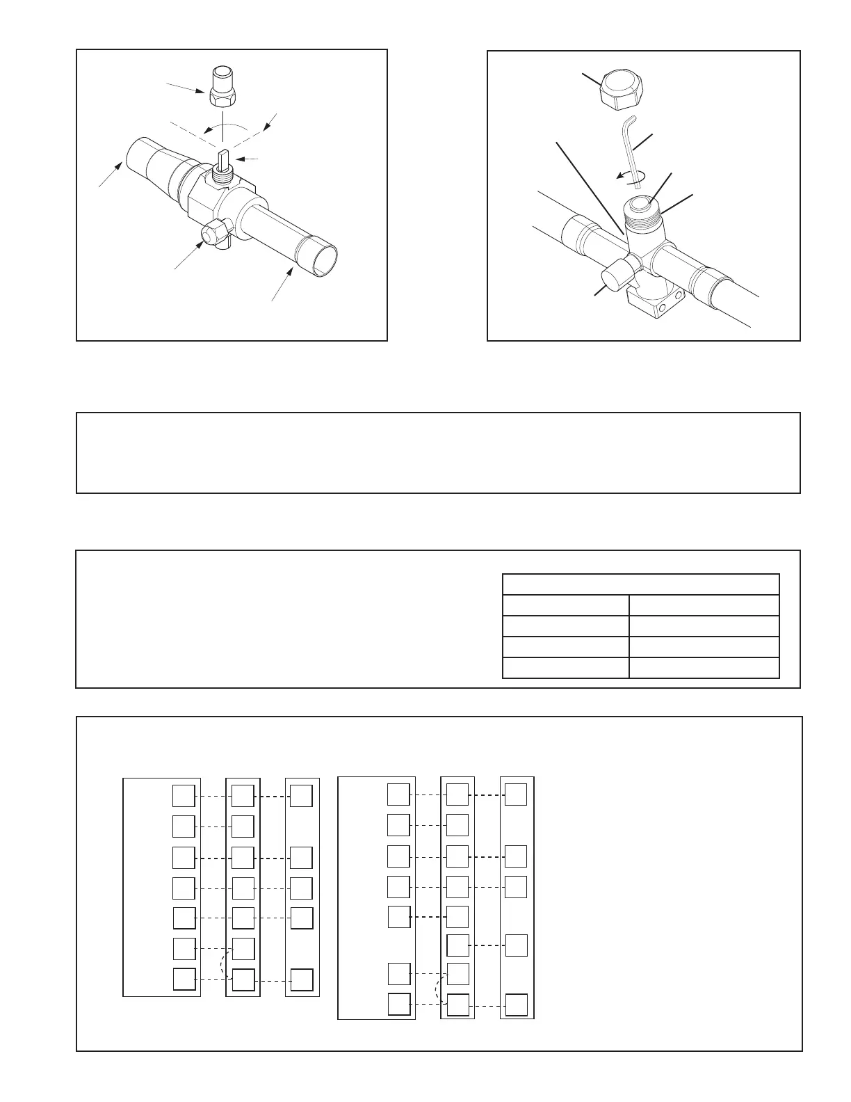
CAP
1/4 TURN ONLY
COUNTERCLOCKWISE
FOR FULL OPEN
POSITION
VALVE STEM
GAS LINE CONNECTION
UNIT SIDE
OF VALVE
PRESSURE TAP PORT
Cap
Rolled Edge to
Captivate Stem
Hex Headed
Valve System
Service Port
3/16” Hex Wrench
Unit Side
of Service
Valve
Gas Service Valve Liquid Service Valve
• The approved ID/OD combination will provide sufficient safe ventilation in case of a leak.
• Refer Indoor Unit Installer’s Guide for correct specifications on indoor unit install.
• All systems require mitigation boards so on altitude adjustment factors required.
• MCB neds to be included in an A2L System.
Mitigation Board Guidelines
Section 11. Electrical - Low Voltage
11.1 Low Voltage Maximum Wire Length
Table 11.1 defines the maximum total length of
low voltage wiring from the outdoor unit, to the
indoor unit, and to the thermostat.
Table 11.1
24 VOLTS
WIRE SIZE MAX. WIRE LENGTH
18 AWG 150 Ft.
16 AWG 225 Ft.
14 AWG 300 Ft.
11.2 Low Voltage Hook-up Diagrams
With 5TEM4, 5, C
Thermostat Air Handler
Outdoor
Unit
R
G
B
W1
W2
R
B
O
Y
X2
R
G
B/C
O
Y
W
Blue
24 VAC HOT
FAN
24 VAC
Common
SOV
COOL/HEAT
1st STAGE
HEATING
2nd STAGE
EMERGENCY
HEAT
Pink Black
White
X2
O
Y*
With 5TAM5, X
Thermostat Air Handler
Outdoor
Unit
R
G
B
W1
W2
R
B
O
Y
O
Y
O
X2
R
G
B/C
O
Y
l
W
Blue
O
Y
l
24 VAC HOT
FAN
24 VAC
Common
SOV
COOL/HEAT
1st STAGE
HEATING
2nd STAGE
EMERGENCY
HEAT
Pink Black
White
X2
•
Units with pigtails require wirenuts for connections.
•
In AC systems for multiple stages of electric heat,
jumper W1 and W2 together if comfort control has
only one stage of heat.
.
* Y2 for TEM6