18-BC118D1-1A-EN 3
Table 2.2
When mounting the outdoor unit on a roof, be sure the roof will support the unit’s weight.
Properly selected isolation is recommended to alleviate sound or vibration transmission to the building structure.
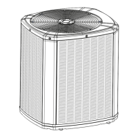
Unit Dimensions and Weight
Models H x D x W (in)
Weight* (lb)
5TWR5018A 33 x 30 x 33 174
5TWR5024A 33 x 30 x 33 174
5TWR5030A 33 x 30 x 33 174
5TWR5036A 37 x 34 x 37 199
5TWR5042A 45 x 34 x 37 250
5TWR5048A 45 x 34 x 37 250
5TWR5060A 45 x 34 x 37 251
* Weight values are estimated uncrated.
Section 2. Unit Location Considerations
2.1 Piping Guidelines
Piping material, pipe routing, and installation shall include protection from physical damage in operation and
service, and be in compliance with national and local codes and standards. All field joints shall be accessible for
inspection prior to being covered or enclosed. Install of pipe work shall be kept to a minimum.
That provisions shall be made for expansion and contraction of long runs of piping.
2.2 Unit Dimensions and Weight
D
H
W
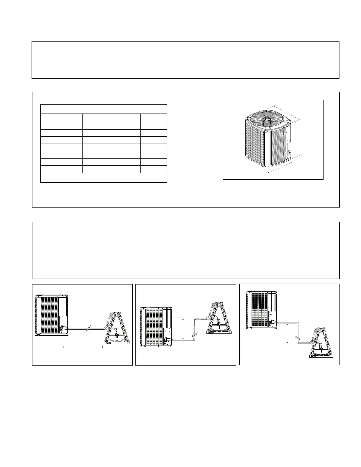
Standard
Line Set
150’ Max
TOTAL Line Length
50’
Max
Vertical
Change
50’
Max
Vertical
Change
2.3 Refrigerant Piping Limits
1. The maximum TOTAL length of refrigerant lines from outdoor to indoor unit should NOT exceed 150 feet
(including lift).
2. The maximum vertical change should not exceed 50 feet.
3. Service valve connection diameters are shown in Table 5.1.
Note: For other line lengths, refer to Refrigerant Piping Application Guide, SS-APG006F-EN, or Refrigerant
Piping Software Program.