18-BC118D1-1A-EN 5
Section 5. Refrigerant Line Considerations
5.1 Refrigerant Line and Service Valve Connection Sizes
Table 5.1
Line Sizes Service Valve Connection Sizes
Model
Vapor
Line
Liquid
Line
Vapor Line
Connection
Liquid Line
Connection
5TWR5018A 5/8 5/16 3/4 5/16
5TWR5024A 3/4 5/16 3/4 5/16
5TWR5030A 3/4 5/16 3/4 5/16
5TWR5036A 3/4 5/16 3/4 5/16
5TWR5042A 7/8 5/16 7/8 5/16
5TWR5048A 7/8 5/16 7/8 5/16
5TWR5060A 7/8 3/8 7/8 3/8
Alternate Refrigerant Line and Service Valve Connection Sizes
Line Sizes Service Valve Connection Sizes
Model
Vapor
Line
Liquid
Line
Vapor Line
Connection
Liquid Line
Connection
5TWR5018A 5/8 3/8 3/4 5/16
5TWR5024A 3/4 3/8 3/4 5/16
5TWR5030A 3/4 3/8 3/4 5/16
5TWR5036A 3/4 3/8 3/4 5/16
5TWR5042A 7/8 3/8 7/8 5/16
5TWR5048A 7/8 3/8V 7/8 5/16
5TWR5060A 7/8 3/8 7/8 3/8
5.4 Refrigerant Line Insulation
Important: The Vapor Line must always be
insulated. DO NOT allow the Liquid Line and
Vapor Line to come in direct (metal to metal)
contact.
Vapor Line
Liquid Line
Insulation
Line Length
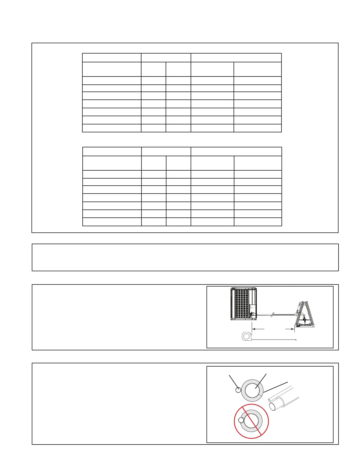
5.3 Required Refrigerant Line Length
Determine required line length and lift. You will
need this later in STEP 2 of Section 14.
Total Line Length = __________ Ft.
Total Vertical Change (lift) = __________ Ft.
5.2 Factory Charge
The outdoor condensing units are factory charged with the system charge required for the outdoor condensing
unit, ten (10) feet of tested connecting line, and the smallest rated indoor evaporative coil match. Always verify
proper system charge via subcooling (TXV/EEV) or superheat (fixed orifice) per the unit nameplate.