Page 2
INSTALLER'S GUIDE ADDENDUM
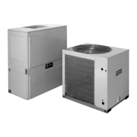
Comfort Control *
Series 7 Air Handler
Air Conditioner
Two Stage Cooling
Neatly bundle all low voltage
wires behind the service
valve cover as shown.
Field wiring
Yellow/Black
Blue
Red
Yellow
Green
Brown
Orange
Blue
B
W
G
Y1
Y2
R
O
O
R
B
YI
W1
YO
Y2
BK
G
W2
W3
(In)
SPDT Relay
w/24 VAC Coil
NO
NC
Y1
O
B
YO
(Out)
Shown in de-energized position
Yellow
/Red
Brown
Notes:
* Heat Pump thermostat is required. Must be set in Heat Pump configuration.
1. It is recommend to use the enhanced mode blower delay profile. See the
Installer’s Guide for S2-3 and S2-4 settings.
2. Wiring must be made as shown for proper operation.
Hydronic
Control
Typical Boiler
Wiring
B
T
T
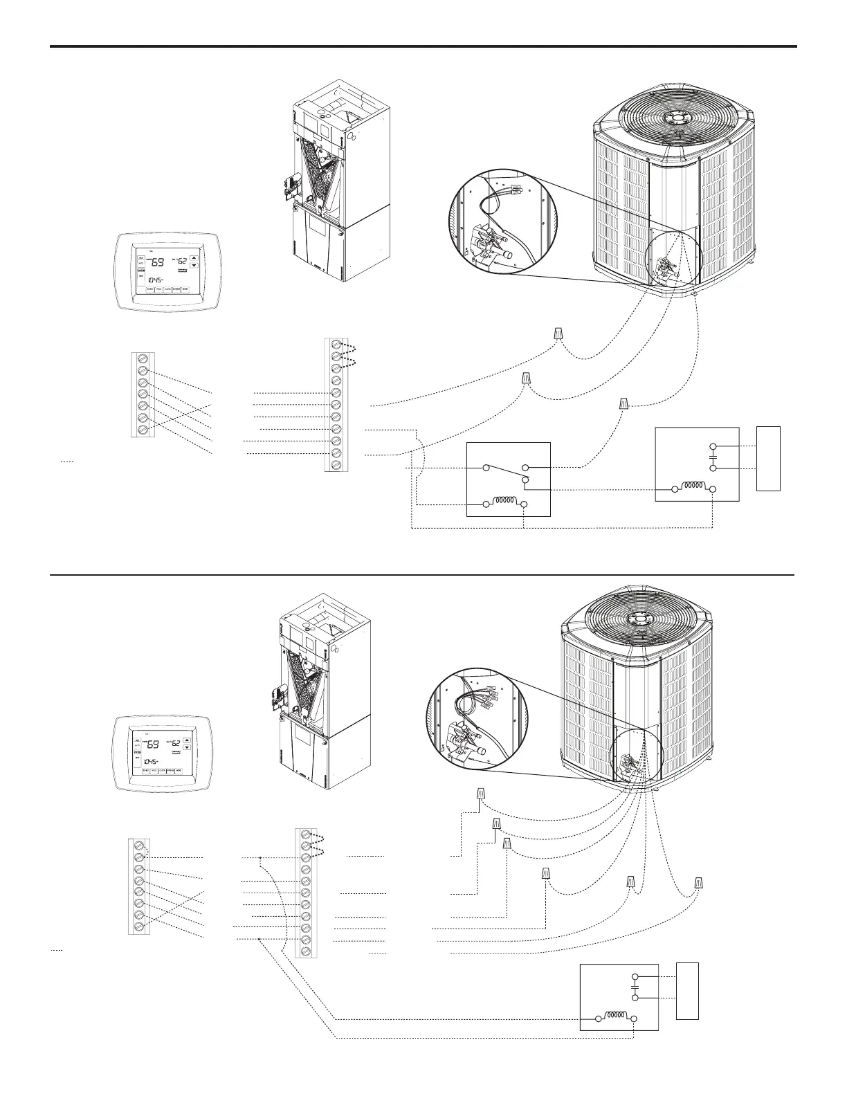
Comfort Control
Series 7 Air Handler
Neatly bundle all low voltage
wires behind the service
valve cover as shown.
Field wiring
Yellow
Yellow/Red
Blue
Black
(X2)
Red
Orange
Red
Yellow
Brown
Orange
Green
White
Blue
B
Y2
B - Blue
W
X2
G
Y1
Y1 - Yellow
Y2 - Brown
R
O
O
R
B
YI
Y2
W1
YO
BK
G
W2
W3
R - Red
O - Orange
(In)
(Out)
W1 - White
Two Stage Heat Pump
Notes:
1. Emergency heat mode only delivers 50% airflow.
2. Hydronic heat is designed for supplemental heat during
compressor operation.
3. It is recommend to use the enhanced mode blower delay
profile. See the Installer’s Guide for S2-3 and S2-4 settings.
4. Wiring must be made as shown for proper operation.
Hydronic
Control
Typical Boiler
Wiring
B
W
T
T
 Loading...