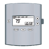
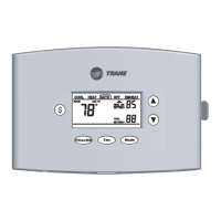
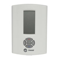
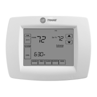
824 Programmable Comfort Control
18-HD72D1-1 page 11
Diagram 9 - 1 Stage Cooling w/Non-Variable Speed Gas Furnace
Diagram 10 - 1 or 2 Stage Cooling w/Variable Speed Gas Furnace
AUX 2
AUX 1
24VAC HOT
COMMON
SOV
COOLING
FA N
HEATING
ODT
RS
AUX2
AUX2
AUX1
AUX1
RC
RH
B/C
O
Y1 Y
Y2
G
BK
W1
W2
W3
ODT
ODT
RS1
RS1
R
B
W3
G
W1
W2
B
Y
Optional
Outdoor
Sensor
Optional
Remote
Sensor
824 COMFORT CONTROL
9- 1 Stage Cooling w/Non-Variable Speed Gas Furnace
INDOOR UNIT
OUTDOOR UNIT
AUX 2
AUX 1
24VAC HOT
COMMON
SOV
COOLING
FA N
HEATING
ODT
RS
AUX2
AUX2
AUX1
AUX1
RC
RH
B/C
O O
Y1
Y2Y2
Y1/Ylo
Y/Y2
G
BK
BK
W1
W2
W3
ODT
ODT
RS1
RS1
R R
B
W3
G
W1
W2
B
Y
Optional
Outdoor
Sensor
Optional
Remote
Sensor
NOTES:
1. Cut and remove the factory installed “BK” jumper at
the indoor unit IFC Board
2. ”R” & “Y2” connections at outdoor are only required
for two stage units
3. ”Y1/Ylo and/or Y/Y2” must be connected at indoor
for non-Trane/American Standars units
824 COMFORT CONTROL
10- 1 or 2 Stage Cooling w/Variable Speed Gas Furnace
INDOOR UNIT OUTDOOR UNIT
3
3
1
 Loading...
