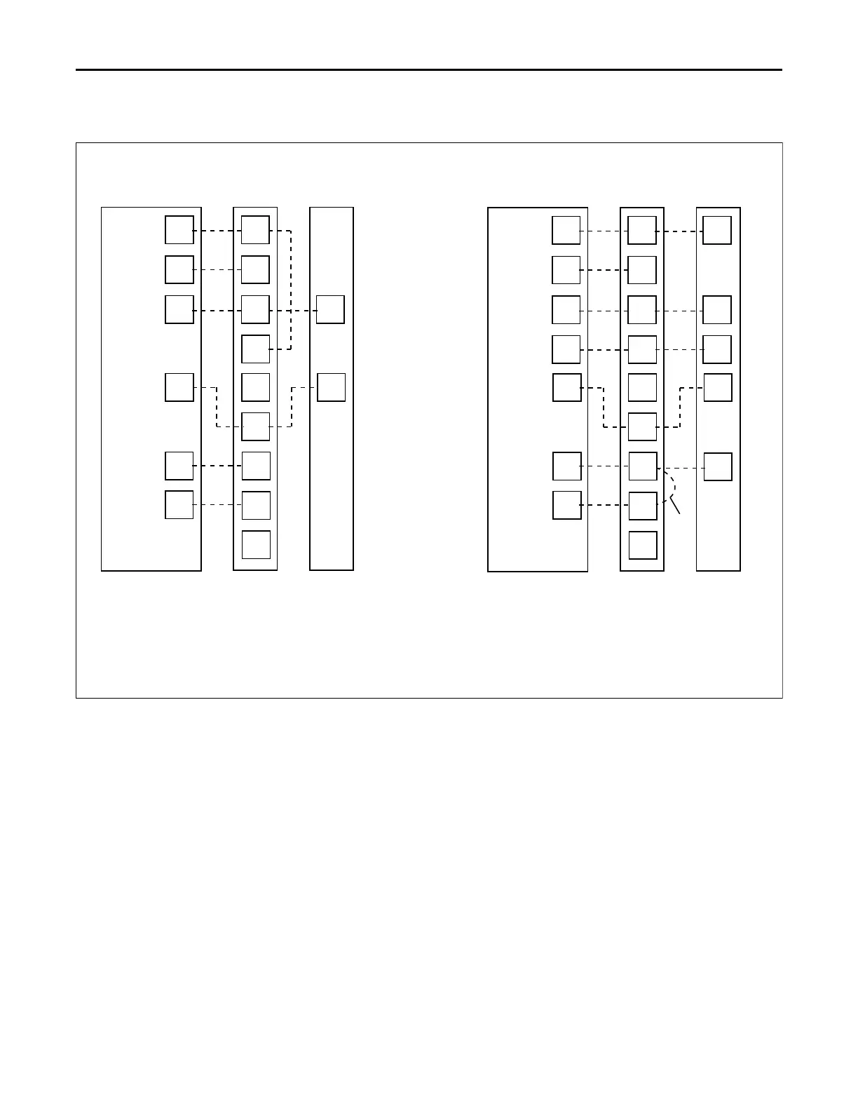
Single Stage, Cooling Only
Thermostat Air Handler
Outdoor
Unit
R
G
B
W1
W2
B
Y
R
G
B
Y
W1
Blue
24 VAC HOT
FAN
24 VAC
Common
SOV
COOL/HEAT
1st STAGE
HEATING
2nd STAGE
EMERGENCY
HEAT
White
White
W2
O
Y1
1. * Units with pigtails require wirenuts for connections.
2. Cap all unused wires.
3. For BK enabled comfort control, do not connect Y1 or Y2 at the air
handler
Y2
BK
WH/BLK
4. For BK enabled comfort control, cut the jumper wire between R
and BK on the control board. See wiring schematic for details.
5. In AC systems for multiple stages of electric heat, jumper W1 and W2
together if comfort control has only one stage of heat.
Single Stage, HP
Thermostat Air Handler
Outdoor
Unit
R
G
B
W1
W2
R
B
O
Y
X2
R
G
B
O
Y
W1
Blue
24 VAC HOT
FAN
24 VAC
Common
SOV
COOL/HEAT
1st STAGE
HEATING
2nd STAGE
EMERGENCY
HEAT
White
Black
White
W2
O
Y1
Y2
BK
Optional
WH/BLK
1. * Units with pigtails require wirenuts for connections.
2. Cap all unused wires.
3. For BK enabled comfort control, do not connect Y1 or Y2 at the air
handler
4. For BK enabled comfort control, cut the jumper wire between R
and BK on the control board. See wiring schematic for details.
5. In systems for multiple stages of electric heat, jumper W1 and W2
together if comfort control has only one stage of heat.
 Loading...
