4 88-A4HP4001-1G-EN
D
W
H
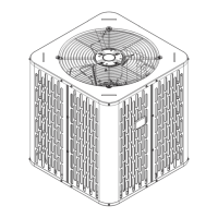
Section 2. Unit Location Considerations
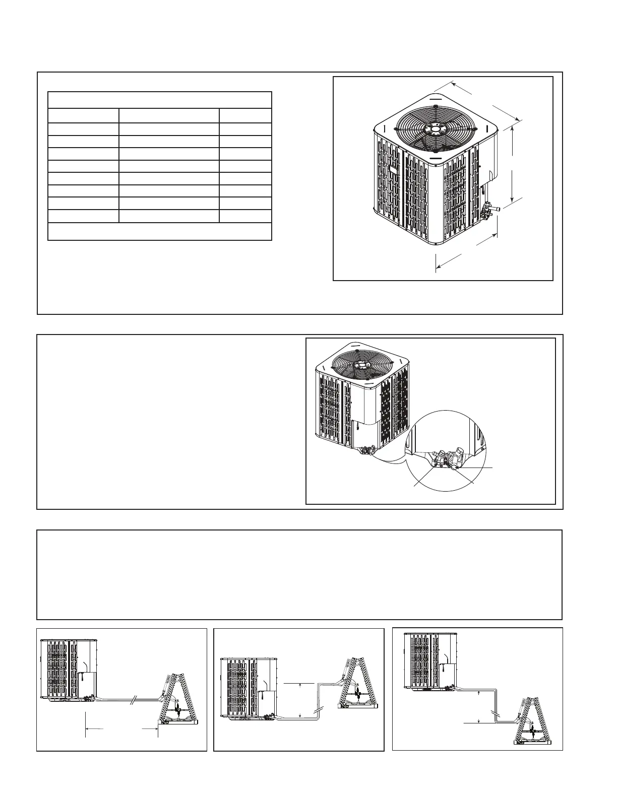
2.1 Unit Dimensions and Weight
Table 2.1
When mounting the outdoor unit on a roof, be sure the
roof will support the unit’s weight.
Properly selected isolation is recommended to alleviate
sound or vibration transmission to the building
structure.
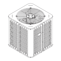
Liquid Line Connection
Access valve for compressor
suction pressure measurement
Suction Line
Connection
2.2 Service Valves Locations
1. The locations of the below listed valves in
the unit are shown in the figure.
a) Liquid line connection
b) Access valve for compressor suction
pressure measurement
c) Suction line connection
Unit Dimensions and Weight
Models H x D x W (in)
Weight* (lb)
A4HP4017D 28.6 X 25.6 X 25.6 143
A4HP4018D 32.6 X 29.8 X 29.8 162
A4HP4024D 32.6 X 29.8 X 29.8 162
A4HP4030D 28.6 X 29.8 X 29.8 159
A4HP4036D 36.6 X 34.3 X 34.3 199
A4HP4042D 44.6 X 34.3 X 34.3 227
A4HP4048D 44.6 X 34.3 X 34.3 250
A4HP4060D 44.6 X 34.3 X 34.3 250
* Weight values are estimated uncrated.
2.3 Refrigerant Piping Limits
1. The maximum TOTAL length of refrigerant lines from outdoor to indoor unit should NOT exceed 150 feet
(including lift).
2. The maximum vertical change should not exceed 50 feet.
3. Service valve connection diameters are shown in Table 5.1.
Note: For other line lengths, refer to Refrigerant Piping Application Guide, SS-APG006F-EN, or Refrigerant
Piping Software Program.
50’
Max
Vertical
Change
50’
Max
V
e
rtical
Ch
ange
Standard
Line Set
150’ Max
TOTAL Line Length