EasyManua.ls Logo

Trane A4HP4 User Manual

Trane A4HP4
32 pages
To Next Page IconTo Next Page
Page #1 background imageLoading...
Page #1 background image
88-A4HP4001-1G-EN
ALL phases of this installation must comply with NATIONAL, STATE AND LOCAL CODES
IMPORTANTThis Document is customer property and is to remain with this unit. Please return to service informa-
tion pack upon completion of work.
These instructions do not cover all variations in systems or provide for every possible contingency to be met in connection with
the installation. Should further information be desired or should particular problems arise which are not covered sufficiently for the
purchaser’s purposes, the matter should be referred to your installing dealer or local distributor.
Note: The manufacturer recommends installing only approved matched indoor and outdoor systems. All of the manufacture’s split
systems are A.H.R.I. rated only with TXV/EEV indoor systems. Some of the benefits of installing approved matched indoor and
outdoor split systems are maximum efficiency, optimum performance and the best overall system reliability.
Table of Contents
Section 1. Safety ..................................................................................... 2
Section 2. Unit Location Considerations.............................................. 4
Section 3. Unit Preparation .................................................................... 5
Section 4. Setting the Unit ..................................................................... 5
Section 5. Refrigerant Line Considerations ......................................... 6
Section 6. Refrigerant Line Routing ..................................................... 7
Section 7. Refrigerant Line Brazing ...................................................... 8
Section 8. Refrigerant Line Leak Check ............................................... 9
Section 9. Evacuation ............................................................................. 9
Section 10. Service Valves ..................................................................... 9
Section 11. Electrical - Low Voltage ................................................... 10
Section 12. Electrical - High Voltage .................................................. 11
Section 13. Start Up .............................................................................. 12
Section 14. System Charge Adjustment ............................................. 12
Section 15. Checkout Procedures ....................................................... 16
Section 16. Defrost Control ................................................................. 17
Section 17. Troubleshooting ................................................................ 20
Section 18. Wiring Diagrams ............................................................... 22
Section 19. Pressure Curves ............................................................... 27
Section 20. Refrigerant Circuit (only for reference)........................... 32
Heat Pumps
A4HP4
Installation and Operation Manual
Question and Answer IconNeed help?

Do you have a question about the Trane A4HP4 and is the answer not in the manual?

Trane A4HP4 Specifications

General IconGeneral
ModelA4HP4
TypeHeat Pump
RefrigerantR-410A
StagesSingle-stage
Voltage208/230V
Phase1
SEER Rating14
HSPF Rating8.2
Compressor TypeScroll
Sound Level (Outdoor Unit)76 dB

Summary

Section 1. Safety

Live Electrical Components Safety

Safety precautions for live electrical components during installation and service.

Hazardous Voltage Warning

Disconnect power before servicing to prevent severe injury or death.

Hot Compressor Dome Caution

Avoid touching hot compressor domes to prevent burns.

Refrigerant Handling Caution

Follow proper procedures to avoid injury or equipment damage from refrigerant.

Brazing and Leak Test Requirement

Ensure leak tests are negative when using mechanical connections for brazing.

R-410A Refrigerant Warning

Units use R-410A refrigerant, requiring approved service equipment and procedures.

Liquid Line Service Valve Caution

Caution when opening liquid line service valve to prevent abrupt release of charge.

Hot Surface Warning

Avoid touching hot surfaces to prevent burns or property damage.

Grounding Requirement

Ensure proper grounding for electrical safety and to prevent damage.

California Proposition 65 Warning

Product may expose to chemicals known to cause cancer or birth defects.

Service Valve Caution

Extreme caution needed when opening service valves to prevent charge release.

Section 2. Unit Location Considerations

Unit Dimensions and Weight

Provides dimensions and weight specifications for different models.

Service Valves Locations

Identifies locations of service valves for connections and measurements.

Refrigerant Piping Limits

Specifies maximum total length and vertical change for refrigerant lines.

Suggested Locations for Best Reliability

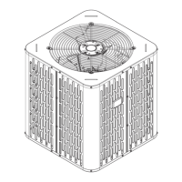
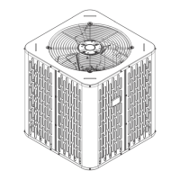
Recommendations for optimal unit placement to ensure airflow and prevent issues.

Cold Climate Considerations

Precautions for units in areas with snow and freezing temperatures.

Section 3. Unit Preparation

Prepare The Unit For Installation

Step to check for and report any damage to the unit before installation.

Section 4. Setting the Unit

Pad Installation

Guidelines for installing the unit on a support pad, including levelness and drainage.

Section 5. Refrigerant Line Considerations

Refrigerant Line and Service Valve Connection Sizes

Table detailing line sizes and service valve connection sizes for various models.

Factory Charge

Information on factory-charged units and verifying system charge.

Required Refrigerant Line Length

Instructions to determine required line length and lift for charging calculations.

Refrigerant Line Insulation

Importance of insulating the vapor line and preventing metal-to-metal contact.

Reuse Existing Refrigerant Lines

Precautions for reusing existing refrigerant lines and coils.

Section 6. Refrigerant Line Routing

Precautions

Guidelines for routing refrigerant lines to prevent noise and comply with codes.

Section 7. Refrigerant Line Brazing

Braze The Refrigerant Lines

Step-by-step instructions for brazing refrigerant lines to service valves and filter driers.

Section 8. Refrigerant Line Leak Check

Check For Leaks

Procedure to pressurize lines with nitrogen and check for leaks using soapy solution.

Section 9. Evacuation

Evacuate the Refrigerant Lines and Indoor Coil

Steps to evacuate the system to a specific micron level.

Section 10. Service Valves

Open the Gas Service Valve

Procedure for opening the gas service valve after leak check and evacuation.

Open the Liquid Service Valve

Procedure for safely opening the liquid service valve with caution.

Section 11. Electrical – Low Voltage

Low Voltage Maximum Wire Length

Table defining maximum wire lengths for low voltage connections.

Low Voltage Hook-up Diagrams

Diagrams illustrating low voltage wiring for heat pump and AC systems.

Defrost Control

Explains defrost control operation, termination, and jumper settings.

Section 12. Electrical – High Voltage

High Voltage Power Supply

Notes on high voltage power supply requirements and compliance with codes.

High Voltage Disconnect Switch

Requirement to install a separate disconnect switch at the outdoor unit.

High Voltage Ground

Grounding requirements for the outdoor unit per national and local codes.

Section 13. Start Up

System Start Up

Step-by-step procedure for starting the system after installation.

Section 14. System Charge Adjustment

Temperature Measurements

Instructions for taking temperature measurements for system charging.

Subcooling Charging in Cooling (Above 55º F Outdoor Temp.)

Method for charging systems using TXV/EEV based on subcooling.

Subcooling Charging in Cooling (Continued)

Charts and steps for determining subcooling corrections based on line length and lift.

STEP 3 - Stabilize the system

Requirement to stabilize the system for 20 minutes before measurements.

STEP 4 - Measure the liquid line temperature and pressure

Measuring liquid line temperature and pressure for charging.

STEP 5 - Use the final subcooling value, refrigerant temperature and pressure

Determining liquid gage pressure using subcooling and temperature charts.

R-410A Refrigerant Charging Chart

Chart to determine liquid gage pressure based on final subcooling and liquid temperature.

STEP 6 - Adjust refrigerant level

Procedure for adding or recovering refrigerant to match chart values.

STEP 7 - Stabilize the system.

Steps to stabilize the system and remove gauges after charging.

STEP 8 - Verify typical performance.

Referencing pressure curves to verify system performance.

Fixed Orifice Superheat Charging Table

Table for determining superheat for systems with fixed orifice metering devices.

STEP 9 - Record System Information for reference.

Recording system pressures and temperatures after charging.

Subcooling Charging Below 55º F Outdoor Temp. (In Heating Only)

Method for determining additional charge for longer line sets in heating mode.

Calculating Charge Using the Weigh-In Method

Procedure for calculating refrigerant charge using the weigh-in method.

STEP 3 - Check the liquid line temperature and liquid gage pressure

Checking liquid line temp and pressure for subcooling in heating.

STEP 4 - Add charge if a minimum of 10º subcooling is not obtained

Adding charge if target subcooling is not met.

STEP 5 - Return to site for adjustment.

Returning for adjustment in cooling mode when ambient is above 55°F.

Section 15. Checkout Procedures and Troubleshooting

Operational And Checkout Procedures

Final inspection and checkout list for proper operation and performance.

Section 16. Defrost Control

Defrost Control Operation

Explains how the demand defrost control measures temperatures and determines defrost needs.

Fault Detection

How fault conditions are indicated by the Fault LED on the control board.

PIN Identification

Identifies test pins (TEST_COMMON, FRC_DFT) on the defrost control board.

Defrost Control Checkout

Checks for normal operation including status LED, voltage, and defrost initiation.

Test Sensors

Procedure to unplug and measure sensor resistance for testing.

Defrost Control Thermistor Table

Table relating temperature to thermistor resistance for defrost control.

DEMAND DEFROST QUICK SPECS

Quick specifications for demand defrost features and parameters.

LED FAULT CODES

Lists LED fault codes, descriptions, and control behaviors.

LED FAULT CODES (Continued)

Continues listing LED fault codes and their corresponding defrost control behavior.

Notes for Defrost Control

Explains adaptive limp modes, lockout periods, and fault clearing conditions.

Section 17. Troubleshooting

Troubleshooting: Compressor Fails to Start

Flowchart to diagnose why the compressor fails to start.

Troubleshooting Outdoor TXV / Heating Mode

Flowchart for troubleshooting TXV and heating mode issues.

Troubleshooting: Compressor Won't Run

Flowchart to diagnose compressor not running issues, checking voltage and components.

Section 18. Wiring Diagrams

17D, 18D, 24D, 30D & 36D Models Wiring Diagrams

Wiring diagrams for specific heat pump models.

42D Models Wiring Diagrams

Wiring diagrams for the 42D heat pump models.

48D & 60D Models Wiring Diagrams

Wiring diagrams for the 48D and 60D heat pump models.

Wiring Diagram Legend

Explains symbols, wire colors, and terminal designations used in wiring diagrams.

Hazardous Voltage Warning

Safety warning about disconnecting power before servicing.

Canadian Installation Voltage Caution

Warning for Canadian installations regarding voltage limits.

Copper Conductors Only Caution

Warning to use only copper conductors for unit terminals.

Section 19. Pressure Curves

Checking Cooling Performance

Instructions for checking cooling performance using pressure curves.

Pressure Curves for A4HP4017D1

Pressure charts for the A4HP4017D1 model in cooling and heating modes.

Pressure Curves for A4HP4018D1

Pressure charts for the A4HP4018D1 model in cooling and heating modes.

Pressure Curves for A4HP4024D1

Pressure charts for the A4HP4024D1 model in cooling and heating modes.

Pressure Curves for A4HP4030D1

Pressure charts for the A4HP4030D1 model in cooling and heating modes.

Pressure Curves for A4HP4036A1

Pressure charts for the A4HP4036A1 model in cooling and heating modes.

Pressure Curves for A4HP4042A1

Pressure charts for the A4HP4042A1 model in cooling and heating modes.

Pressure Curves for A4HP4048A1

Pressure charts for the A4HP4048A1 model in cooling and heating modes.

Pressure Curves for A4HP4060A1

Pressure charts for the A4HP4060A1 model in cooling and heating modes.

Section 20. Refrigerant Circuit (only for reference)

Heating Refrigeration Cycle

Diagram illustrating the refrigerant flow during the heating cycle.

Cooling Refrigeration Cycle

Diagram illustrating the refrigerant flow during the cooling cycle.

Related product manuals