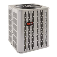
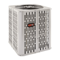
This document is an installer's guide for Trane and American Standard Heat Pumps, specifically models A4HP5018D1000A, A4HP5024D1000A, A4HP5030D1000A, A4HP5036D1000A, A4HP5042D1000A, A4HP5048D1000A, and A4HP5060D1000A. It provides comprehensive instructions for the safe and proper installation, startup, and maintenance of these outdoor condensing units.
Function Description:
These heat pumps are designed for residential heating, ventilating, and air-conditioning applications, creating comfortable and energy-efficient indoor environments. They operate using R-410A refrigerant and are intended for use with matching indoor evaporative coils. The guide covers the entire installation process, from unit placement and preparation to refrigerant line connections, electrical wiring, system startup, and charge adjustment. It also includes troubleshooting information for common system faults.
Important Technical Specifications:
- Refrigerant Type: R-410A. This refrigerant operates at 50 to 70% higher pressures than R-22, necessitating the use of R-410A approved service equipment.
- Compressor Oil: POE oil, which readily absorbs moisture from the atmosphere. Systems should remain sealed whenever possible to limit hygroscopic action. If a system is open to the atmosphere for more than 4 hours, the compressor oil must be replaced.
- Refrigerant Line Length Limits:
- Maximum total length (outdoor to indoor unit, including lift): 150 feet.
- Maximum vertical change (lift): 50 feet.
- Service Valve Connection Sizes:
- Models A4HP5018D, A4HP5024D, A4HP5030D: Vapor Line 3/4", Liquid Line 3/8".
- Models A4HP5036D, A4HP5042D, A4HP5048D, A4HP5060D: Vapor Line 7/8", Liquid Line 3/8".
- Factory Charge: Units are factory charged with the system charge required for the outdoor condensing unit, ten (10) feet of tested connecting line, and the smallest rated indoor evaporative coil match.
- Low Voltage Wiring:
- 18 AWG: Max. 150 Ft.
- 16 AWG: Max. 225 Ft.
- 14 AWG: Max. 300 Ft.
- Defrost Control: Defrost terminates at 47°F as shipped. Jumper J2 can be cut to achieve a 70°F termination temperature.
- Unit Dimensions and Weight (Estimated Uncrated):
- A4HP5018D, A4HP5024D: 32.6" H x 29.8" W x 29.8" D, 162 lb.
- A4HP5030D: 28.6" H x 29.8" W x 29.8" D, 159 lb.
- A4HP5036D: 36.6" H x 34.3" W x 34.3" D, 199 lb.
- A4HP5042D: 44.6" H x 34.3" W x 34.3" D, 227 lb.
- A4HP5048D, A4HP5060D: 44.6" H x 34.3" W x 34.3" D, 250 lb.
Usage Features:
- Installation Location:
- Ensure top discharge area is unrestricted for at least five (5) feet above the unit.
- Provide three (3) feet clearance in front of the control box (access panels) and any other side requiring service.
- Maintain a minimum of 12" from any wall or surrounding shrubbery for adequate airflow.
- Avoid locations near bedrooms or windows where noise or defrost vapor may be an issue.
- For cold climates, elevate units 3-12 inches above the pad/rooftop to allow for drainage of snow and ice. Avoid snow drift accumulation or install a barrier.
- Pad Installation: The support pad should be at least 1" larger than the unit on all sides, separate from any structure, level, and high enough above grade for drainage.
- Refrigerant Line Routing: Take precautions to prevent noise/vibration transmission. Use isolation type hangers when fastening lines to joists/framing. Insulate and isolate lines running through walls or sills. Minimize 90º turns.
- Brazing: Use a deburring tool and emery cloth to clean pipe ends. Purge lines and indoor coil with dry nitrogen. Wrap a wet rag around valve body to avoid heat damage during brazing. Install drier in the liquid line.
- Leak Check: Pressurize lines and evaporator coil to 150 PSIG with dry nitrogen and check for leaks with soapy solution.
- Evacuation: Evacuate until micron gauge reads no higher than 350 microns. Evacuation is complete if the micron gauge does not rise above 500 microns in one (1) minute after closing the valve to the vacuum pump.
- Service Valve Operation: Open gas service valve 1/4 turn counterclockwise to fully open. Open liquid line service valve counterclockwise until the valve stem just touches the rolled edge (approximately five turns). Replace valve stem caps and tighten finger tight plus an additional 1/6 turn.
- Electrical Connections: High voltage power supply must match nameplate. Power wiring must comply with national, state, and local codes. Install a separate disconnect switch at the outdoor unit. Ground the outdoor unit per code requirements. Flexible electrical conduit is recommended for high voltage connections to prevent vibration.
- System Start Up:
- Ensure all installation steps are complete.
- Set thermostat to OFF.
- Turn on disconnect(s) to apply power.
- Wait one (1) hour before starting if compressor crankcase heater accessory is used and outdoor ambient is below 70°F.
- Set thermostat to ON.
- System Charge Adjustment:
- Subcooling (TXV/EEV): Recommended for outdoor temperatures above 55°F. Use provided charts to determine final subcooling value based on line length and lift. Stabilize system for 20 minutes before making adjustments.
- Weigh-In Method (Heating Only): Recommended for outdoor temperatures below 55°F. Calculate additional charge based on line length (0.6 oz/ft for interconnecting tubing beyond 10 ft).
- Superheat (Fixed Orifice): Use the provided table based on indoor wet bulb and outdoor dry bulb temperatures. Add refrigerant to decrease superheat, remove to increase. Allow 10-15 minutes for stabilization after adjustments.
Maintenance Features:
- General Inspection: Perform a final unit inspection to ensure factory tubing has not shifted, wiring connections are tight, and tubes do not rub against each other.
- Checkout Procedure: Verify refrigerant lines are leak-free and insulated, connections are secure, passages through masonry are sealed, electrical connections are tight, outdoor fan operates smoothly, indoor coil drain line drains freely, supply registers and return grilles are open, return air filter is installed, correct airflow setting is used, and the complete system operates safely in each mode.
- Troubleshooting: The guide includes a detailed troubleshooting table for common system faults, categorizing them by refrigerant circuit, electrical issues, and defrost problems. It lists primary and secondary causes for each fault, indicating whether it applies to cooling (C) or heating (H) modes.