4 88-A5AC5001-1A-EN
D
W
H
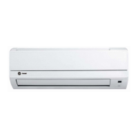
Section 2. Unit Location Considerations
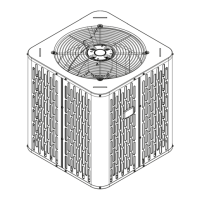
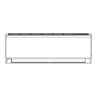
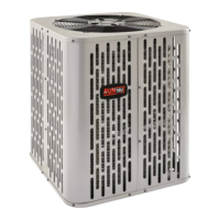
2.1 Unit Dimensions and Weight
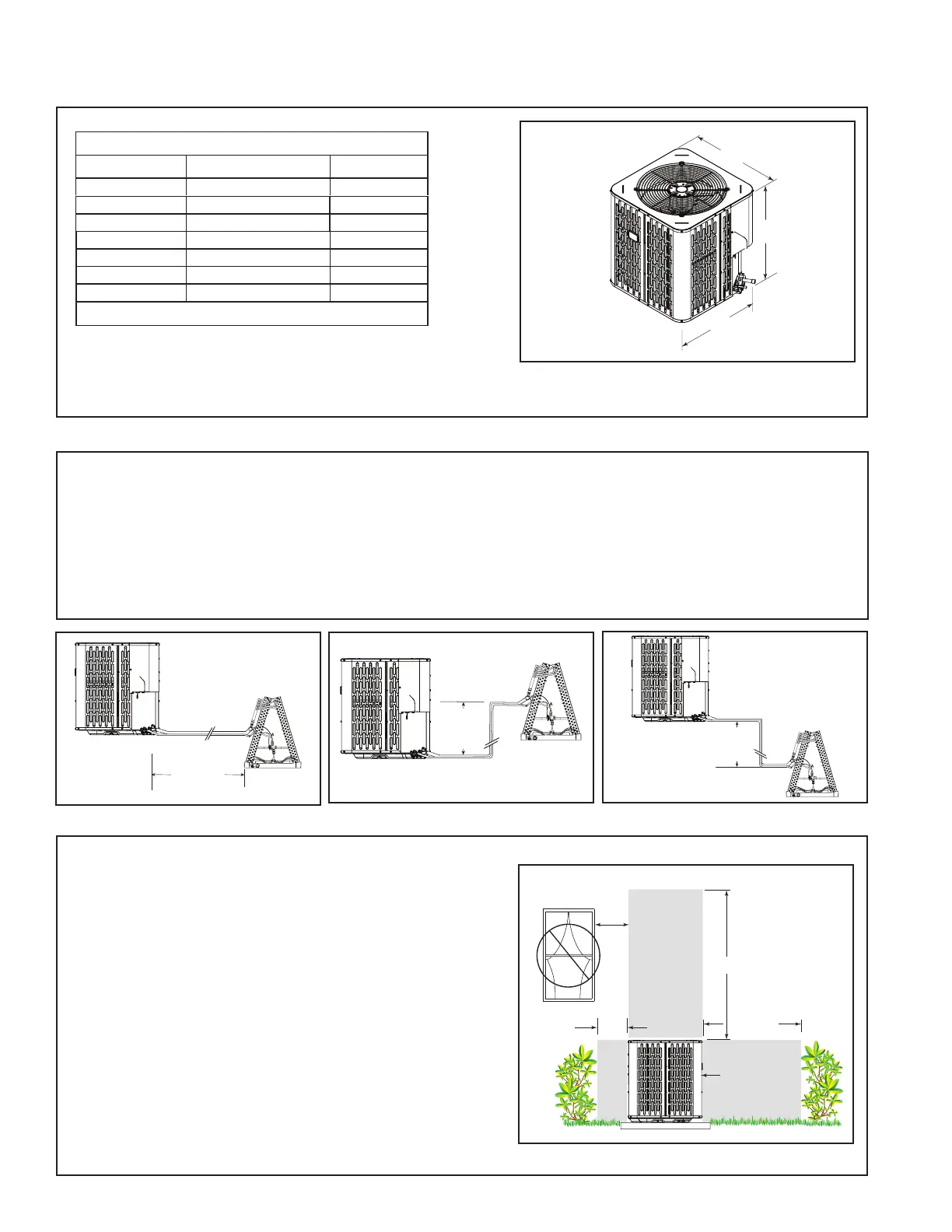
2.2 Refrigerant Piping Limits
Table 2.1
When mounting the outdoor unit on a roof, be sure the roof will support the unit’s weight.
Properly selected isolation is recommended to alleviate sound or vibration transmission to the building structure.
1. The maximum TOTAL length of refrigerant lines from outdoor to indoor unit should NOT exceed 150 feet*
(including lift).
2 . The maximum vertical change should not exceed 50 feet*.
3 . Standard and alternate line sizes and service valve connection sizes are shown in Table 5.1.
* See Table 5.1 for exceptions for certain tonnages.
Note: For other line lengths, Refer to Refrigerant Piping Application Guide, SS-APG006F-EN, or Refrigerant
Piping Software Program.
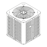
Min. 12” to
Shrubbery
Avoid Install
Near Bedrooms
Min 5’ Unrestricted
Access Panel
Min 3’
Unrestricted
2.3 Suggested Locations for Best Reliability
Ensure the top discharge area is unrestricted for at least
five (5) feet above the unit.
Three (3) feet clearance must be provided in front of the
control box (access panels) and any other side requiring
service.
It is not recommended to install in a location where noise
may distract the building occupants. Some examples
of these types of locations are sleeping quarters and by
windows of a living area. Please discuss location with the
building owner prior to installation.
Avoid locations such as near windows where condensation
and freezing defrost vapor can annoy a customer.
Position the outdoor unit a minimum of 12” from any wall or
surrounding shrubbery to ensure adequate airflow.
Outdoor unit location must be far enough away from any
structure to prevent excess roof runoff water or icicles from
falling directly on the unit.
Unit Dimensions and Weight
Models H x D x W (in) Weight* (lb)
A5AC5018A
36.6 x 29.8 x 29.8
184
A5AC5024A
161
A5AC5030A
36.6 x 29.8 x 29.8
184
A5AC5036A
32.6 x 29.8 x 29.8
161
A5AC5042A
36.6 x 34.3 x 34.3 212
A5AC5048A
44.3 x 34.3 x 34.3
252
A5AC5060A 44.3 x 34.3 x 34.3 252
* Weight values are estimated.
Standard
Line Set
60’ Max
Line Length
32.6 x 29.8 x 29.8