Do you have a question about the Trane A5AC5018A and is the answer not in the manual?
Covers hazardous voltage, refrigerant, hot surfaces, fire risk, brazing, and ventilation hazards.
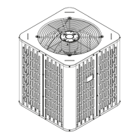
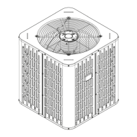
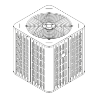
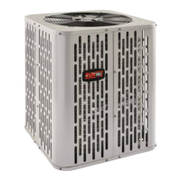
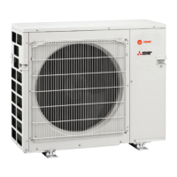
Details physical specifications and weight for outdoor units.
Specifies maximum total length and vertical change for refrigerant lines.
Guidance on optimal placement for performance and service access.
Precautions for units installed in areas with snow and freezing temperatures.
Steps for initial unit inspection and readiness for installation.
Guidelines for selecting and preparing the unit support pad.
Table of line sizes and valve connections for different models.
Information on the initial refrigerant charge from the factory.
Specifies maximum total length and vertical change for refrigerant lines.
Guidelines for insulating the vapor and liquid refrigerant lines.
Precautions for using existing refrigerant lines in retrofit applications.
Guidelines for secure and noise-free installation of refrigerant lines.
Step-by-step instructions for brazing refrigerant lines to service valves.
Procedures for pressure testing and detecting leaks in refrigerant lines.
Steps for achieving and verifying system vacuum before charging.
Guidelines for safe refrigerant recovery, handling, and system servicing.
Procedure for correctly opening the gas service valve.
Procedure for correctly opening the liquid service valve.
Table specifying maximum wire lengths based on wire gauge.
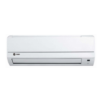
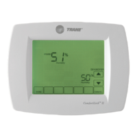
Wiring diagrams for connecting thermostat, air handler, and outdoor unit.
Warning about hazards of working with live electrical components.
Requirement to install a separate disconnect switch at the outdoor unit.
Procedure for grounding the outdoor unit according to codes.
Step-by-step procedure for powering up and starting the system.
Measuring outdoor and indoor temperatures for charging.
Method for charging systems using TXV/EEV based on subcooling.
Detailed steps for adjusting system refrigerant charge using subcooling.
Procedure for calculating and adding refrigerant by weight.
Checklist for final system checks and operational verification.
Diagrams illustrating the refrigeration flow for specific model series.
Diagrams illustrating the refrigeration flow for specific model series.
Diagrams illustrating the refrigeration flow for specific model series.
Electrical wiring schematics for models 018 through 048.
Electrical wiring schematics for model 060.
Displays pressure curves for model A5AC5018A1 for cooling performance.
Displays pressure curves for multiple models including A5AC5024A1, A5AC5030A1, etc.
Displays pressure curves for model A5AC5060A1.
| Model | A5AC5018A |
|---|---|
| Type | Split System Air Conditioner |
| Refrigerant | R-410A |
| Voltage | 208/230V |
| Phase | 1 |
| Sound Level | 72 dB |
| HSPF Rating | Not Applicable |
| Compressor Type | Single Stage |
| Stages | Single Stage |
| Cooling Capacity | 18, 000 BTU/H |