
A
ahaasAug 18, 2025
What happens when Trane Arctic Manhattan Gen II Chiller shows HP Alarm?
- ZZachary BakerAug 18, 2025
When a Trane Chiller displays an HP Alarm, the system shuts down Circuit 1/2.
What happens when Trane Arctic Manhattan Gen II Chiller shows HP Alarm?
When a Trane Chiller displays an HP Alarm, the system shuts down Circuit 1/2.
What happens when Trane Arctic Manhattan Gen II shows LP Alarm?
When a Trane Chiller displays an LP Alarm, the system shuts down Circuit 1/2.
What happens when Trane Arctic Manhattan Gen II shows HP Switch Alarm?
When a Trane Chiller displays an HP Switch Alarm, the system shuts down Circuit 1/2.
What happens when Trane Arctic Manhattan Gen II Chiller shows LP Lockout Alarm?
When a Trane Chiller displays an LP Lockout Alarm, the system shuts down Circuit 1/2.
What does it mean when my Trane Arctic Manhattan Gen II says 'Primary communication lost'?
If the Trane Chiller indicates that the primary communication is lost, the secondary modules switch into Stand-alone Mode.
What does 'Phase Monitor Alarm' mean on my Trane Arctic Manhattan Gen II Chiller?
If the Trane Chiller indicates a Phase Monitor Alarm, the module will be locked out.
What does 'c.pCOe Offline Alarm' mean on my Trane Arctic Manhattan Gen II?
If the Trane Chiller indicates a c.pCOe Offline Alarm, the system shuts down Circuit 2.
What does 'c.pCOe UI2 sensor failure' mean on my Trane Arctic Manhattan Gen II Chiller?
If the Trane Chiller indicates a c.pCOe UI2 sensor failure, the system shuts down Circuit 2.
What does 'Condenser LWT too low' mean on my Trane Arctic Manhattan Gen II?
The Trane Chiller is issuing a warning because the Condenser LWT is too low.
What does 'c.pCOe UI1 sensor failure' mean on my Trane Chiller?
If the Trane Chiller indicates a c.pCOe UI1 sensor failure, the system shuts down Circuit 2 if Low Pressure sensor selected for Suction Pressure Alarm.
Defines the three types of safety advisories: Warning, Caution, and Notice.
Emphasizes the necessity of qualified personnel for safe electrical installation.
Mandates the use of appropriate PPE to prevent serious injury during servicing.
Instructions for recording chiller model and serial numbers for future reference.
Explains how model numbers provide information about chiller features.
Details the available tonnage and modular connection capabilities of the chiller.
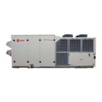
Describes the main components of a chiller, including the Copeland compressor.
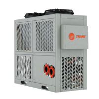
Describes the optional tank and pump module that can be equipped with the chiller.
Details the necessary steps and checks before the initial startup of the chiller system.
Procedure for inspecting delivered equipment for visible and concealed damage upon receipt.
Guidelines for proper storage conditions to prevent equipment degradation during dormancy.
Details requirements for site preparation and maintaining adequate clearances around the chiller.
Specifies minimum clearance requirements for proper airflow and service access.
Provides safety guidelines and methods for rigging, lifting, and moving the chiller unit.
Instructions for correctly filling the chiller's hydronic system with water/glycol mixture.
Details on connecting power and control wiring between chiller modules.
Instructions for installing and verifying the phase monitor for electrical protection.
Overview of the automated system's main electrical panel for monitoring and control.
Explains the function of each module's electrical and control panel for component distribution.
Instructions on how to operate the microprocessor via the touchscreen interface.
Details on using the touchscreen interface for adjusting set points and performing setups.
Covers HMI software version, user management, and access to module layout and alarms.
Lists all active and non-active alarms, providing details on source value, state, and description.
Displays historical alarm data, allowing sorting by various criteria like time and description.
Provides screens to monitor and maintain conditions affecting individual chiller modules.
Screens for monitoring analog and digital input/output data from module sensors and controls.
Displays real-time and historical trends for temperatures and demand, aiding performance analysis.
Procedure for starting the chiller after a scheduled shutdown or power interruption.
Provides guidance on maintaining the correct glycol concentration for freeze protection.
Discusses methods and importance of using glycol for burst protection against freezing.
Describes the Carel c.pCO control system and its microprocessor controllers.
Describes the phase monitor's role in ensuring proper electricity configuration for compressor safety.
Discusses considerations for operating the chiller in high or low ambient temperature conditions.
Describes the operational logic for a constant flow chiller system.
Explains the operational logic for a variable flow system without a tank and pump module.
Outlines a preventive maintenance approach to avoid equipment failure and restore reliability.
Routine daily inspection tasks to monitor chiller performance and identify obvious problems.
Monthly inspection tasks to identify and address small problems before they escalate.
Comprehensive quarterly inspections to identify and repair potential chiller issues early.
Critical annual inspections to ensure long-term chiller performance and prevent major issues.
Specific maintenance steps for chillers equipped with a tank and pump module.
Procedure for cleaning evaporator strainers to protect heat exchanger passages.
Steps for cleaning condenser coils to maintain chiller performance, especially in high ambient conditions.
Detailed procedure for safely removing a compressor from the chiller module.
Step-by-step guide for installing a new compressor into the chiller module.
Procedure for safely removing a pump or pump motor from the chiller.
Instructions for installing a new pump, including connections and verification.
Procedure for replacing the Programmable Logic Controller (PLC) in the chiller module.
Methodology for identifying and isolating faults within the chiller system for timely repairs.
Explanation of alarm codes displayed on the remote interface panel for fault identification.
Details on flash codes communicated by Copeland compressors indicating abnormal conditions.
A guide listing common troubleshooting symptoms and their potential solutions.
Simplified block diagram illustrating the high voltage power flow within a chiller module.
Diagram showing the low voltage circuits for controller and sensor connections.
Illustrates the independent refrigeration circuits within each chiller module.
A comprehensive list of acronyms and abbreviations used throughout the manual.
Details the typical components found in a tank and pump module assembly.
Instructions for filling the pressurized storage tank with water/glycol mixture.
Checklist of mandatory tasks required to be completed before initial startup.