Do you have a question about the Trane BAYCO2K011A and is the answer not in the manual?
The Trane CO2 Sensing Kit is an installation guide for a carbon dioxide (CO2) sensing kit designed for use with Trane IntelliPak™ 120-130 Ton Rooftops, Air Handler 2-9 Casings, IntelliPak™ II 90-162 Ton Rooftops, and Air Handler A-C Casings. This kit is crucial for maintaining optimal indoor air quality and energy efficiency in commercial and residential applications.
The primary function of the CO2 Sensing Kit is to detect and control the carbon dioxide level within a conditioned space. It achieves this by continuously measuring CO2 concentration and comparing it against a user-adjustable set point, which is typically configured via the Human Interface of the associated HVAC system. When the CO2 concentration exceeds the set point, the sensor sends a signal to the economizer damper. This signal causes the economizer damper to adjust its position, introducing a sufficient amount of fresh outdoor air into the conditioned space. The goal is to reduce and maintain the CO2 concentration at or below the selected minimum level, thereby ensuring good indoor air quality and occupant comfort.
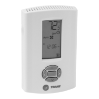
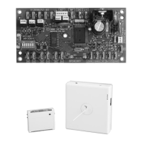
The kit includes two main types of CO2 sensors: a wall-mounted sensor (BAYCO2K011A) and a duct-mounted sensor (BAYCO2K012A). Both sensors serve the same fundamental purpose of CO2 detection and control, but they are designed for different installation environments. The wall-mounted sensor is ideal for direct measurement within the occupied space, while the duct-mounted sensor is suitable for monitoring CO2 levels within the return or supply air ducts of the HVAC system.
An economizer must be installed and fully functional before attempting to install the CO2 Sensing Kit. This prerequisite highlights the integrated nature of the CO2 sensor with the broader HVAC system's ventilation capabilities. The sensor acts as a critical input for demand-controlled ventilation (DCV) strategies, allowing the HVAC system to modulate outdoor air intake based on actual occupancy and CO2 levels rather than fixed schedules. This not only improves indoor air quality but also contributes significantly to energy savings by reducing the amount of outdoor air that needs to be heated or cooled.
The CO2 Sensing Kit offers straightforward installation and integration with compatible Trane HVAC units. For wall-mounted sensors, proper placement is emphasized: an interior wall with good air circulation, approximately 54 inches (1.4 meters) from the floor, is recommended to ensure accurate readings representative of the occupied space. The installation process involves removing the back plate, threading power and output signal wires, and then securely mounting the back plate to the wall. The circuit board is then inserted into the back plate, taking care not to press the metal tube.
For duct-mounted sensors, the installation involves drilling a 7/8-inch to 1-inch hole in the mounting surface of the duct. The mounting plate is then attached to the duct wall with screws, and the sensor is inserted through the mounting plate. The depth of insertion can be adjusted for optimal air sensing within the ductwork. If conduit is required for wiring, the kit provides instructions for removing the wiring grommet and installing a supplied 1/2-inch National Pipe Thread (NPT) conduit fitting.
A key usage feature for both sensor types is the ability to configure the output type. On the circuit board, two jumpers located next to the terminal block allow technicians to set the output to either 0-10 Vdc, 0-20 mA, or 4-20 mA. For IntelliPak II systems, the default setting is 4-20 mA, but it needs to be changed to 0-10 Vdc for proper integration. This flexibility ensures compatibility with various control systems and wiring configurations.
Wiring instructions are provided for both IntelliPak I and IntelliPak II systems. For IntelliPak II, the sensor's ground terminal (terminal 0) is wired to 1TB6-18, which in turn connects to J7-3 on the VCM (Ventilation Control Module). The voltage output terminal V(OUT) on the sensor is wired to 1TB6-17, connecting to J7-2 on the VCM. For IntelliPak I, a table specifies the wiring connections: 24V to 1XD25-1, OUT to 1XD25-2, and GND to 1XD25-3. These 1XD25 terminals are factory wired to the 1KF11 board, specifically to J5-3 for 1XD25-1, J3-3 for 1XD25-2, and J3-4 for 1XD25-3. These detailed wiring instructions ensure correct electrical connection and communication between the CO2 sensor and the HVAC unit's control system.
The kit also includes a "CO2 Kit installed" label, which should be affixed to the equipment after installation. This label serves as a clear indicator that the demand-controlled ventilation system is in place, potentially aiding in future maintenance or inspections.
While the manual primarily focuses on installation, it implicitly highlights several aspects related to maintenance and safety. The emphasis on "Only qualified personnel should install and service the equipment" underscores the need for professional expertise in handling these devices. This ensures that installation is performed correctly, minimizing the likelihood of issues that would require subsequent maintenance.
The "ASAFETY WARNING" sections throughout the manual are critical for safe maintenance practices. They cover hazardous voltage, proper field wiring and grounding, and the mandatory use of personal protective equipment (PPE). For instance, the warning to "Disconnect all electric power, including remote disconnects before servicing" is a fundamental safety precaution that applies directly to any maintenance or troubleshooting activities involving the sensor or its wiring. Following proper lockout/tagout procedures is essential to prevent inadvertent energization, which could lead to serious injury or death.
The requirement for proper field wiring and grounding, performed by qualified personnel according to NEC and local/state/national electrical codes, ensures the long-term reliability and safety of the installation, reducing the need for corrective maintenance due to electrical faults. Similarly, the detailed instructions on PPE, including cut-resistant gloves, safety glasses, hard hats, and arc flash clothing, are crucial for protecting technicians during any interaction with the equipment, whether during installation, routine checks, or repair.
The inclusion of wire ties (standard and pop-in anchor type) in the parts list suggests an emphasis on neat and secure wiring, which contributes to the longevity and reliability of the electrical connections, thereby reducing potential maintenance issues related to loose or damaged wiring. The plastic bushings for different diameter holes also ensure proper cable management and protection.
Although the manual does not detail specific calibration or cleaning procedures for the CO2 sensor itself, the accurate initial setup of the output type via jumpers is a critical step that ensures the sensor provides correct data to the HVAC system. Any future troubleshooting would likely involve verifying these settings and the integrity of the wiring connections. The overall design for integration with Trane's IntelliPak systems implies that diagnostic tools and maintenance routines for the broader HVAC system would also encompass checking the functionality of the CO2 sensor. The "CO2 Kit installed" label also serves as a quick reference for maintenance personnel to identify the presence of the sensor.
| Compatibility | Trane HVAC Systems |
|---|---|
| Measurement Range | 0-2000 ppm |
| Warranty | 1 year |
| Product Type | Carbon Dioxide Sensor |
| Operating Temperature | 32°F to 122°F (0°C to 50°C) |
| Operating Humidity | 0% to 95% RH, non-condensing |
| Power Supply | 24 VAC/VDC |
| Output Signal | 0-10 VDC |