EasyManua.ls Logo

Trane WTS - User Manual

Trane WTS
52 pages
To Next Page IconTo Next Page
Loading...
Installation, Operation, and
Maintenance
Wireless Sensors
Models WTS, WZS, and WDS
April 2008
BAS-SVX04C-EN

Table of Contents

Questions and Answers:

Trane WTS Specifications

General IconGeneral
CategoryAccessories
Power SourceBattery
DisplayNo
Control TypeWireless
TypeWireless Temperature Sensor
CompatibilityTrane thermostats and controls
Temperature Range32°F to 122°F (0°C to 50°C)

Summary

General Information

Product Description

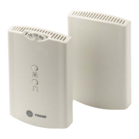
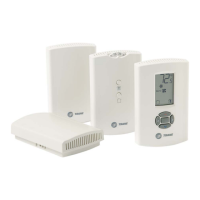
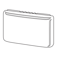
Provides descriptions of the wireless sensor models WDS, WTS, and WZS.

Part Numbers

Lists available wireless sensor models by their part numbers for ordering.

Dimensions

Details the physical dimensions of the wireless sensor units.

Pre-Installation

Location Considerations

Guidance on selecting optimal locations for receivers and sensors to ensure signal reliability.

Height Requirements

Recommendations for mounting height, considering accessibility guidelines.

Mounting Surfaces

Instructions on preparing and mounting surfaces for receivers and sensors.

Address Setting

Procedures for setting unique addresses for receiver-sensor association.

Installation

Receiver Mounting and Wiring

Covers mounting the receiver back plate and wiring it to the unit controller.

Sensor Association and Configuration

Details on associating sensors to receivers and configuring WDS sensor features.

System Testing and Verification

Procedures for testing signal strength, battery status, and system operation.

Sensor Mounting and Cover Replacement

Instructions for mounting the sensor back plate and replacing its cover.

Operation

Temporary Occupancy and Service Requests

How to manage temporary occupancy and initiate service pin requests.

Sensor Functions and Modes

Explains star/double star functions, end-of-range values, and operating modes.

Changing System and Temperature Settings

Guides on adjusting room temp, system settings, and fan settings.

Status Indicators and Error Handling

Information on error codes, lock symbols, and testing signal/battery status.

Maintenance and Troubleshooting

Component Locations and Diagnostics

Identifies LEDs, buttons, symbols, and explains diagnostic procedures.

Signal and Battery Testing

Detailed steps for testing signal strength and battery status.

Battery Replacement and System Association

Procedures for replacing sensor batteries and performing manual association/disassociation.

Troubleshooting Procedures and System Testing

Guides for testing the system, receiver, forcing sensor transmit, and output values.

Cleaning and Output Resistance Measurement

Instructions for cleaning sensors and measuring output resistance.

Specifications

Appendix A: Wiring Diagrams

Single Transformer Wiring

Illustrates the wiring setup using a single transformer for the system.

Multiple Transformer Wiring

Illustrates the wiring setup using multiple transformers for the system.

Appendix B: Agency Compliance

Related product manuals