Do you have a question about the Trane Wired Temperature Sensors and is the answer not in the manual?
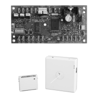
Describes Trane wired temperature sensors and their features, including optional accessories.
Lists part numbers for various sensor types, their features, and optional accessories.
Provides detailed physical dimensions for all sensor models, including mounting hole locations.
Guidelines for selecting optimal sensor placement to avoid environmental interference and ensure accuracy.
Recommended mounting heights for sensors, including considerations for wheelchair accessibility.
Instructions for mounting sensors to various surfaces like sheetrock, plaster, or electrical junction boxes.
Step-by-step instructions for mounting the display sensor's back plate to the wall.
Detailed steps for wiring the display sensor to the unit controller using the terminal block.
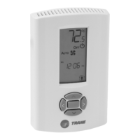
Details configuration steps, options for temperature, setpoint, system, fan, and occupancy settings.
Instructions for checking the display configuration and returning to operating mode.
Covers features like displaying setpoint or locking/unlocking settings for enhanced control.
Instructions for removing and reinstalling the sensor cover, securing it with a screw.
Instructions for mounting the back plate for non-display sensor models.
Steps for wiring non-display sensors to the unit controller.
Guide for installing the optional COMM module for service tool connectivity.
Procedure for changing or replacing the setpoint thumb wheel on compatible sensors.
Instructions for replacing the cover on non-display sensor models.
How to adjust temperature, system, and fan settings on various sensor models using thumb wheels or sliders.
Using timed occupancy, service pin requests, and star/double star functions for enhanced control.
Operating display sensors for temperature, system, and fan settings, including dual setpoints.
Explains error codes and the lock symbol displayed on the sensor for status and troubleshooting.
Explains LEDs, error codes, and output values during sensor failures for troubleshooting.
Procedures for measuring sensor output resistance for troubleshooting sensor functionality.
Guidelines for safely cleaning the sensor and replacing the setpoint thumb wheel.
Wiring diagrams for basic temperature sensors, identified by part numbers.
Wiring diagrams specific to sensors equipped with fan control functionality.
Wiring diagrams for sensors that manage both fan and system control modes.
Wiring diagram illustrating the connections for the optional COMM module accessory.
Detailed technical specifications for sensor operating temperature, humidity, accuracy, and power consumption.
Compliance information for US, Canada, Europe, and CE declaration for the wired sensors.
| Brand | Trane |
|---|---|
| Model | Wired Temperature Sensors |
| Category | Accessories |
| Language | English |