Page 3
INSTALLER'S GUIDE
18-HB22D1-14
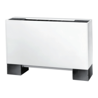
Figure 4
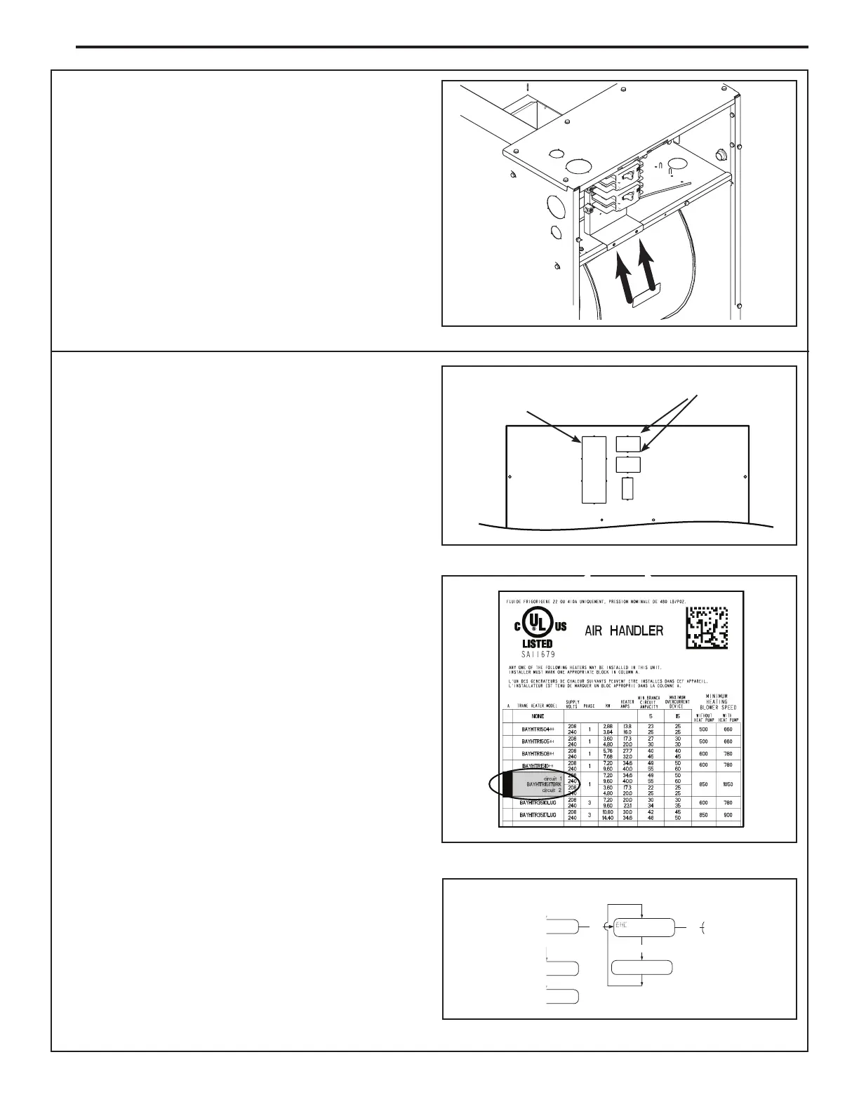
Figure 5
Center knockouts
Left knockout
Figure 6 - New Label shown in place
Figure 7 - Configuration Menu
10. Secure breaker/pull disconnect mount plate with
two screws along the bottom of plate.
11. Make all wiring connections per applicable field
wiring diagrams. All installations must conform to
national, state and local electrical codes.
12. Connect the polarized harness plug to the
polarized plug on the heater.
13. Refer to the heater minimum airflow chart or the
unit rating nameplate for the appropriate minimum
blower speed tap to be used with the approved
heater installed.
14. Connect all field wiring per air handler installation
guide.
Note: For LUG models, do not remove knockouts or
insulation.
15. Remove the appropriate breaker knock-out plates
from Blower Access panel. Cut and remove
insulation behind knock-out.
- IMPORTANT: Left knockout must be used for
the following:
- ALL TEM8A0B24/30 air handlers
- All 25 kW heaters
- All TEM/A4AH4 air handlers installed with a Single
Power Entry Kit ship with a Heater Breaker Seal Kit.
(See Seal Kit Installer's Guide for install instructions.)
Note: Follow the instructions in the Breaker Seal Kit
18-GJ85D1-1 (latest rev). The Breaker Seal Kit
will ship with the TEM8A0B air handlers, 25 KW
heaters and single power entry kits for TEM/A4AH4
air handlers.
- Center knockouts: Use for all other 4-20 kW
heaters installations with all TEM/A4AH4 air
handler (except TEM8A0B24/30).
16. Install Blower Access panel ensuring alignment of
breakers through access panel.
17.
On the unit nameplate, check off the heater that
has been installed or apply the new secondary
nameplate label within the heater data table on the
air handler nameplate as shown in Figure 6.
Note: If using a heater in a TEM4/A4AH4 air handler, go
to Step 18.
18. Cut insulated butt crimp terminal off of heater low
voltage field wires (W1 - White, B/C - Blue)
19. Strip 1/2" insulation from the cut end for field
thermostat wiring termination.
20. For the TEM8 models, set the heater size in the
Configuration Menu.
Select
heat type)
heat)
ic heat)
Select
XXX (capacityinKW)
EHC (electric heat
capacity)
List
Config
Menu
Page 3 of 20 10/16/2019
MOHS, PLANS EXAMINER
REV #1 .
2405 E AINSWORTH AVE B19-2396
INSTALL HVAC SYSTEM/PORT OF PASCO 10/1/2019
 Loading...