11
Installer’s Guide
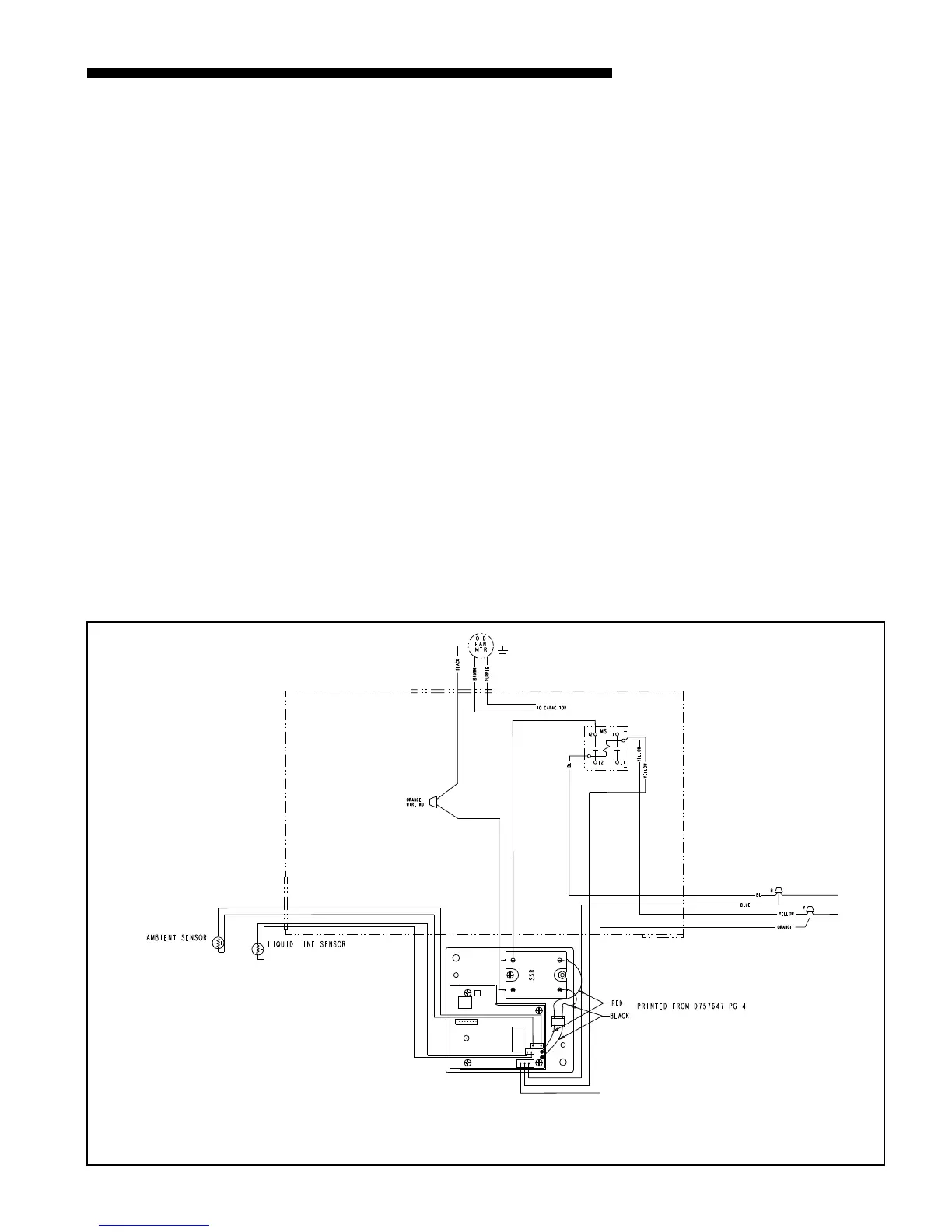
7c 2/4YC** and 4TC** Three Phase 230 Volt Cooling
and Gas/Electric Models. See Figure 13.
Disconnect the black fan motor lead from the
contactor (this wire is attached to contactor terminal
“T2”, with a quick connect terminal). Cut the
terminal off of this wire and strip the end about 1/2
inch. Select one of the black wires from the SSR relay
on the Control Module, cut the terminal off and strip
the end about 1/2 inch. Connect these two ( the black
fan motor lead to the black SSR lead) with a wire nut
supplied.
Connect the other black wire from the SSR to the
contactor terminal “T2” (from where the fan motor
lead was disconnected).
Connect Low voltage wires (BYO):
1. Connect the 3-pin BYO low voltage wire harness
(supplied in kit) to J5 on the Control Module(3-pin
male connector). See Figure 14 on page 12. Note: to
ease the insertion of the connector housing on to the
J5 header, place the connector on the tips of the
three header pins. Angle the connector upward to-
ward the header latch while pushing connector over
the header pins.
2. Connect the yellow lead wire of the harness to a
¼ " male tab on the right hand side of the main
contactor (low voltage contactor coil terminal). See
Figure 13.
3. Connect the blue lead wire of the harness to the
wire nut junction of the blue wire (use new wire
nuts from kit).
4. Connect the orange wire to the wire nut junction
of the yellow wire (use new wire nuts from kit).
5. Connect the Liquid Line Sensor to J2 on the Con-
trol Module.See Figure 14 on page 12.
6. Connect the Outdoor Temperature Sensor (Ambi-
ent Sensor) to J3 on the Control Module.
7. Reinstall louvers and panels. Continue with step 8.
System Setup, Page 14.
Figure 13. 2/4YC** and 4TC** 230/460 volt Three Phase Cooling and Gas/Electric Models
IMPORTANT — Retain this wiring diagram; please return this document to service information pack upon completion of work.
 Loading...


